Semiconductor laser with wide side of tapered light gain region

a technology of light gain and semiconductor laser, applied in the field of semiconductor laser, can solve the problems of reducing the conversion efficiency of electric/optical output, limiting the amount of light output, and inevitably affecting the shape of measuring devices,

Inactive Publication Date: 2000-06-13
NEC CORP
View PDF11 Cites 44 Cited by
  • Summary
  • Abstract
  • Description
  • Claims
  • Application Information

AI Technical Summary

Problems solved by technology

Further, output of light increases along with the injection of current, but there is a limit in the amount of light output since saturation of light output becomes distinct beyond a certain current density.
In the first prior art example, in which it is intended to increase the output by broadening the width of the light output region or by increasing the number of semiconductor lasers through an array arrangement, there is a problem that, since the light emission region is required to be large, the optical system for forming, for example, a measuring device inevitably becomes large.
Thus, because of mode control, there is a limitation also in widening angle of the light emission region such that, in order to increase output, it is necessary to make the length of the resonator.
Such

Method used


Image

  • Semiconductor laser with wide side of tapered light gain region
  • Semiconductor laser with wide side of tapered light gain region
  • Semiconductor laser with wide side of tapered light gain region

Examples


first embodiment

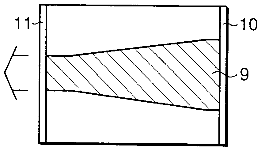
FIG. 5 shows, in a plan view, the flared structure type semiconductor laser of a first embodiment according to the invention, and FIG. 6 shows a diagrammatic sectional view taken along lines 6--6 in FIG. 5. The element shown is fabricated as explained hereinafter. First, an n-InP buffer layer 2 (0.2 .mu.m thick), an active layer 5, and a cladding layer 6 (0.3 .mu.m thick) are sequentially formed on an n-InP substrate 1. The active layer 5 has a multi-quantum well structure with energy bands as shown in FIG. 7, and is constituted by five InGaAsP well layers 25 (8 nm thick) with a compressive strain of +0.8% being introduced, an InGaAsP barrier layer 26 (6 nm thick) with a composition having an emission wavelength of 1.2 .mu.m, and an InGaAsP SCH (Separate Confinement Hetero-structure) layer 27 (50 nm thick) of a composition having an emission wave-length of 1.2 .mu.m. The emission wavelength at the active layer 5 is 1.5 .mu.m. After an SiO.sub.2 insulating film is formed on a semicon...

second embodiment

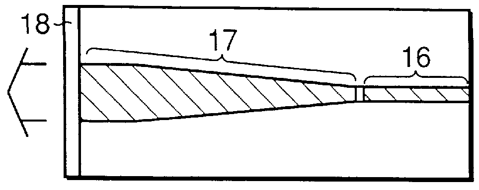
FIG. 8 shows, in a plan view, a flared structure type semiconductor laser of a second embodiment according to the invention, and FIG. 9 shows, in a diagrammatic sectional view, a section taken along lines 9--9 in FIG. 8. The element shown is fabricated as explained hereinafter. First, an n-InP buffer layer 2 (0.2 .mu.m thick), an active layer 5, and a cladding layer 6 (0.3 .mu.m thick) are sequentially formed on an n-InP substrate 1. The active layer 5 has a multi-quantum well structure with energy bands as shown in FIG. 7, and is constituted by five InGaAsP well layers 25 (8 nm thick) with a compressive strain of +0.8% being introduced, an InGaAsP barrier layer 26 (6 nm thick) with a composition having an emission wavelength of 1.2 .mu.m, and an InGaAsP SCH layer 27 (50 nm thick) of a composition having an emission wavelength of 1.2 .mu.m. The emission wavelength at the active layer 5 is 1.5 .mu.m. After an SiO.sub.2 insulating film is formed on a semiconductor wafer, tapered shape...

third embodiment

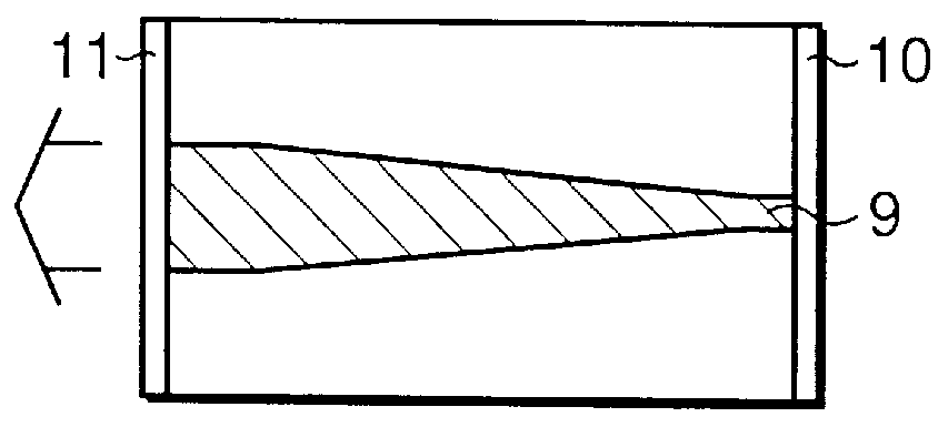
FIG. 10 shows, in a plan view, a flared structure type semiconductor laser of a third embodiment according to the invention, and FIG. 11 shows, in a diagrammatic sectional view, a section taken along lines 11--11 in FIG. 10. The element shown is fabricated as explained hereinafter. First, an n-InP buffer layer 2 (0.2 .mu.m thick), an active layer 5, a cladding layer 6 (2 .mu.m thick), and a p-InGaAs contact layer 7 (0.5 .mu.m thick) having an emission wavelength of 1.64 .mu.m are sequentially formed on an n-InP substrate 1. The active layer 5 has a multi-quantum well structure with energy bands as shown in FIG. 7, and is constituted by five InGaAsP well layers 25 (8 nm thick) with a compressive strain of +0.8% being introduced, an InGaAsP barrier layer 26 (6 nm thick) with a composition having an emission wavelength of 1.2 .mu.m, and an InGaAsP SCH layer 27 (50 nm thick) of a composition having an emission wavelength of 1.2 .mu.m. The emission wavelength of the active layer 5 is 1.5...


PUM


Abstract

The semiconductor laser disclosed includes a first conductivity type buffer layer, an active layer and a second conductivity type cladding layer which are sequentially positioned on a first conductivity type semiconductor substrate. The active layer has a laser gain region to which an electric current is injected. The laser gain region having a width varying linearly along a resonating direction is disposed between a high reflection film provided on a facet of a wide side of the laser gain region of the active layer and a low reflection film provided on a facet of a narrow side of the laser gain region of the active layer. The facet of the narrow side is for outputting oscillation beams of a high order mode. This provides a high electrical-to-optical conversion efficiency, and enables the outputting of a large output from a narrow light emission region.

Description

(1) Field of the InventionThe present invention relates to a semiconductor laser adapted to be used as a light source for optical measuring and solid-state laser excitation, and is capable of operating with a large output of up to several tens of Watts, and more particularly to a semiconductor laser and a composite semiconductor laser in which a large output can be obtained with a narrow optical output region.(2) Description of the Related ArtIn the field of, for example, optical measuring, a device for measuring distance to a given point has been developed. For such a device, there is a need for a high output laser diode as a light source which generates an optical output in the Watt and several tens of Watts classes.For showing structural differences in the semiconductor laser according to the invention as compared with prior art semiconductor lasers, FIG. 1A shows the general structural arrangements of a laser outputting elements according to the invention and FIGS. 1B-1D show th...

Claims


Application Information

Patent Timeline
IPC IPC(8): H01S5/10H01S5/00H01S5/40H01S5/20H01S5/028H01S5/183
CPCH01S5/1064H01S5/028H01S5/187Y10S372/704H01S5/4031H01S5/4043H01S2301/18H01S5/2036
Inventor TAMANUKI, TAKEMASAYAMAZAKI, HIROYUKI
Owner NEC CORP
Why Eureka
Try Eureka