Reagent supply vessel for chemical vapor deposition

a technology of chemical vapor deposition and liquid reagent, which is applied in the direction of liquid transferring devices, transportation and packaging, packaging, etc., can solve the problems of undesirable gas passage up the dip tube in liquid delivery applications, difficult and/or expensive synthesizing of liquid reagents, and high cost of liquid reagents employed

Inactive Publication Date: 2000-06-20
ENTEGRIS INC
View PDF11 Cites 153 Cited by
  • Summary
  • Abstract
  • Description
  • Claims
  • Application Information

AI Technical Summary

Problems solved by technology

In the field of chemical vapor deposition using liquid delivery systems for the supply of a liquid reagent to a vaporizer, wherein the liquid is vaporized by the vaporizer and passed to a chemical vapor deposition reactor for forming the desired material layer on a substrate from the reagent vapor, the liquid reagents employed are often costly.
This is particularly true in instances where the material sought to be deposited in the chemical vapor deposition operation is a precious metal or rare element, or where the liquid reagent is difficult and/or expensive itself to synthesize.
The passage of gas up the dip tube is undesirable in liquid delivery application

Method used


Image

  • Reagent supply vessel for chemical vapor deposition
  • Reagent supply vessel for chemical vapor deposition

Examples


Embodiment Construction

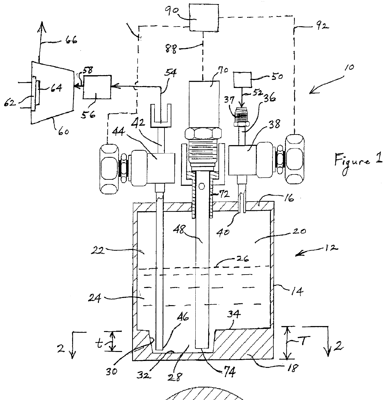
Referring to the drawings, FIG. 1 is a schematic representation of a chemical vapor deposition system 10 including a reagent supply vessel assembly shown in elevation view and partial cross-section, according to an illustrative embodiment of the invention.

In this system, the reagent supply vessel 12 includes side wall member 14, which may for example comprise a cylindrical wall or wall segments corporately defining an enclosing side wall structure, e.g., of square or other non-circular cross-section, top wall member 16 and floor member 18. The side wall, top wall and floor members define an enclosed interior volume 20 of the vessel, which in operation may contain a gas space 22 overlying a liquid 24 defining a liquid surface 26 at the gas-liquid interface.

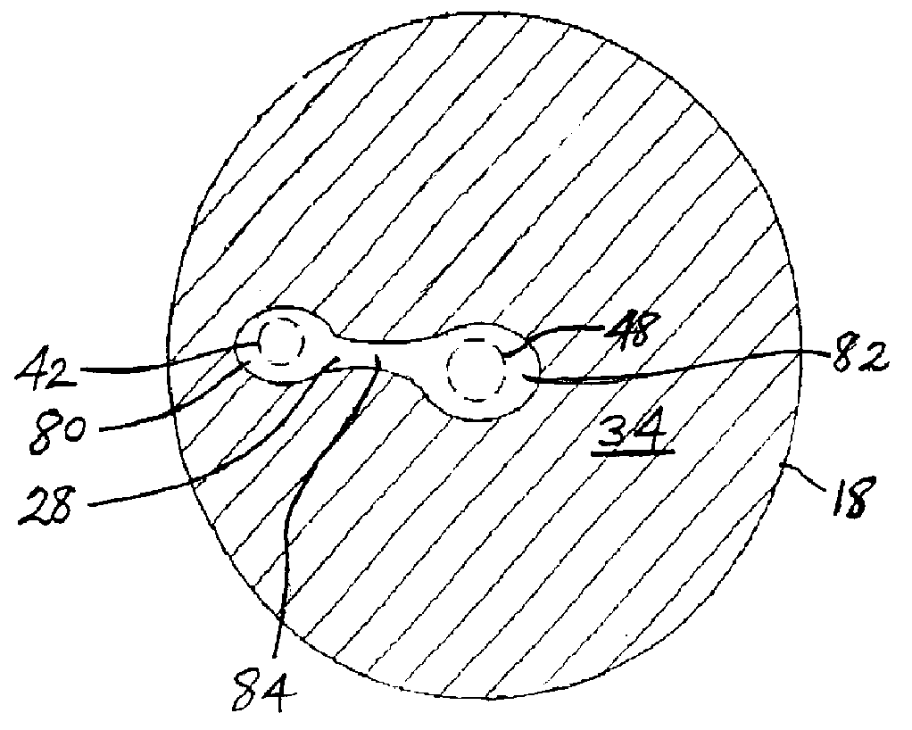
In accordance with the invention, the floor member 18, which as shown in FIG. 1 has a main floor surface 34, is provided with a sump cavity 28 therein. The sump cavity 28 extends downwardly from the main floor surface 34 into the f...


PUM

PropertyMeasurementUnit
Fractionaaaaaaaaaa
Fractionaaaaaaaaaa
Pressureaaaaaaaaaa

Abstract

A liquid reagent dispensing assembly, comprising a gas-pressurizable vessel including a floor, and an interior volume bounded by interior wall and floor surfaces. A dip-tube liquid discharge conduit is employed for discharging liquid from the gas-pressurized vessel. The vessel is provided with a liquid level sensor for sensing liquid reagent level in the vessel interior volume. The floor of the vessel has a cavity therein extending downwardly from the surface of the floor, and the lower end of the dip tube is positioned in the cavity. The dispensing assembly of the invention may usefully be employed for dispensing of reagents such as precursors for deposition of materials in the manufacture of semiconductor materials and devices, and achieves a high level of withdrawal of the reagent liquid from the vessel.

Description

1. Field of the InventionThe present invention relates generally to a closed vessel liquid reagent dispensing assembly of the type in which liquid is dispensed from a dip-tube liquid discharge conduit from a gas-pressurized vessel, and in which the liquid level may be sensed by a sensor extending downwardly in the vessel and terminating just short of the floor thereof.2. Description of the Related ArtIn the field of chemical vapor deposition using liquid delivery systems for the supply of a liquid reagent to a vaporizer, wherein the liquid is vaporized by the vaporizer and passed to a chemical vapor deposition reactor for forming the desired material layer on a substrate from the reagent vapor, the liquid reagents employed are often costly.This is particularly true in instances where the material sought to be deposited in the chemical vapor deposition operation is a precious metal or rare element, or where the liquid reagent is difficult and / or expensive itself to synthesize. Exampl...

Claims


Application Information

Patent Timeline
IPC IPC(8): B67D5/02B67D5/01B67D5/32C23C16/52C23C16/448B01J4/00B67D7/02B67D7/32B65D83/00C23C16/00
CPCB01J4/008B67D7/0238C23C16/52C23C16/448C23C16/4482B67D7/3263C23C16/00
Inventor BOUCHARD, FRED
Owner ENTEGRIS INC
Why Eureka
Try Eureka