SPCVD silicate glasses

a technology of silicate glasses and silicate glass, which is applied in the field of spcvd silicate glasses, can solve the problems that current amplifiers are not well suited for multichannel amplification, and achieve the effects of enhanced multichannel amplifiers, improved gain flatness, and high levels of fluorine, alumina and nitrogen

Inactive Publication Date: 2000-06-20
CORNING INC
View PDF7 Cites 11 Cited by
  • Summary
  • Abstract
  • Description
  • Claims
  • Application Information

AI Technical Summary

Benefits of technology

Our development incorporates a combination of fluorine, Al.sub.2 O.sub.3 and / or Ga.sub.2 O.sub.3 to achieve even wider Er.sup.3+ fluorescence and improved gain flatness in the 1550 nm telecom window. In addition, SPCVD can incorporate large amounts of F, Al.sub.2 O.sub.3 and N into low-loss fiber all of which impact rare earth behavior. The SPCVD produces fiber preforms with high levels of fluorine, alumina, and nitrogen. These heavily fluorinated glasses provide much broader Er.sup.3+ emission than Type I or Type II silica for enhanced multichannel amplifiers. SPCVD successfully fluorinates silica with losses below 5 dB / km and increased Er.sup.3+ emission width.

Problems solved by technology

However, current amplifiers are not well suited for multichannel amplification due to the strong dependence of their gain as a function of wavelength.

Method used


Image

  • SPCVD silicate glasses
  • SPCVD silicate glasses

Examples


example i

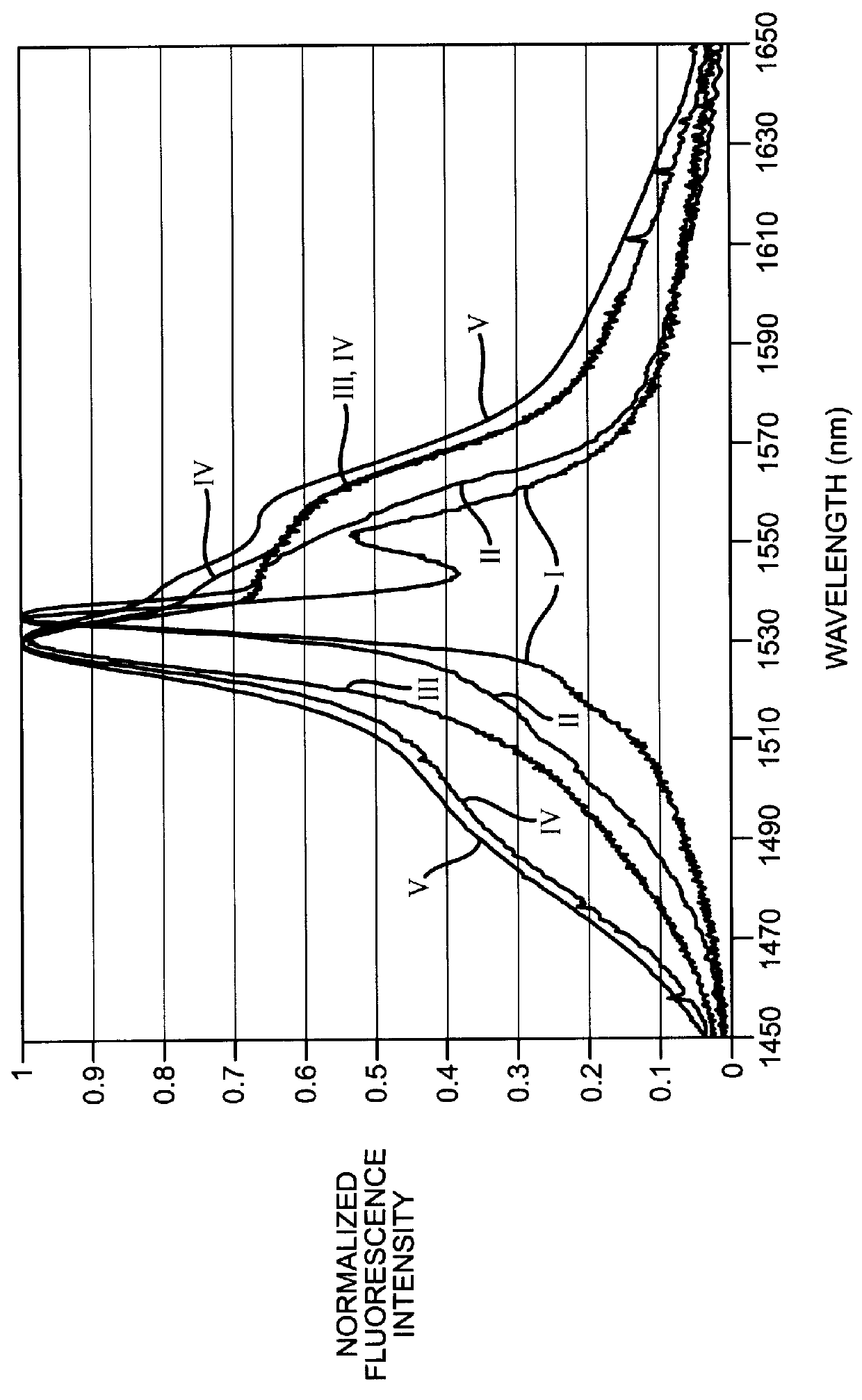
FIG. 1 shows the normalized Er.sup.3+ emission intensity as a function of wavelength. The emission spectra of Er.sup.3+ in pure SiO.sub.2 (curve I) is the narrowest. The additions of fluorine (curve II) and Al.sub.2 O.sub.3 (curve III) significantly broaden the emission from 23 nm to 28 and 44 nm FWHM respectively. Losses of less than 2 dB / km have been achieved in both systems. By combining F and Al.sub.2 O.sub.3, the width is further increased to 50 nm (curve IV). By adding appropriate glass modifiers such as CaO and Ta.sub.2 O.sub.5 or K.sub.2 O and Sb.sub.2 O.sub.3 emission FWHM in excess of 55 nm can be achieved. Curve V shows the Er.sup.3+ fluorescence from a CaO--Ta.sub.2 O.sub.5 --Al.sub.2 O.sub.3 --SiO.sub.2 glass

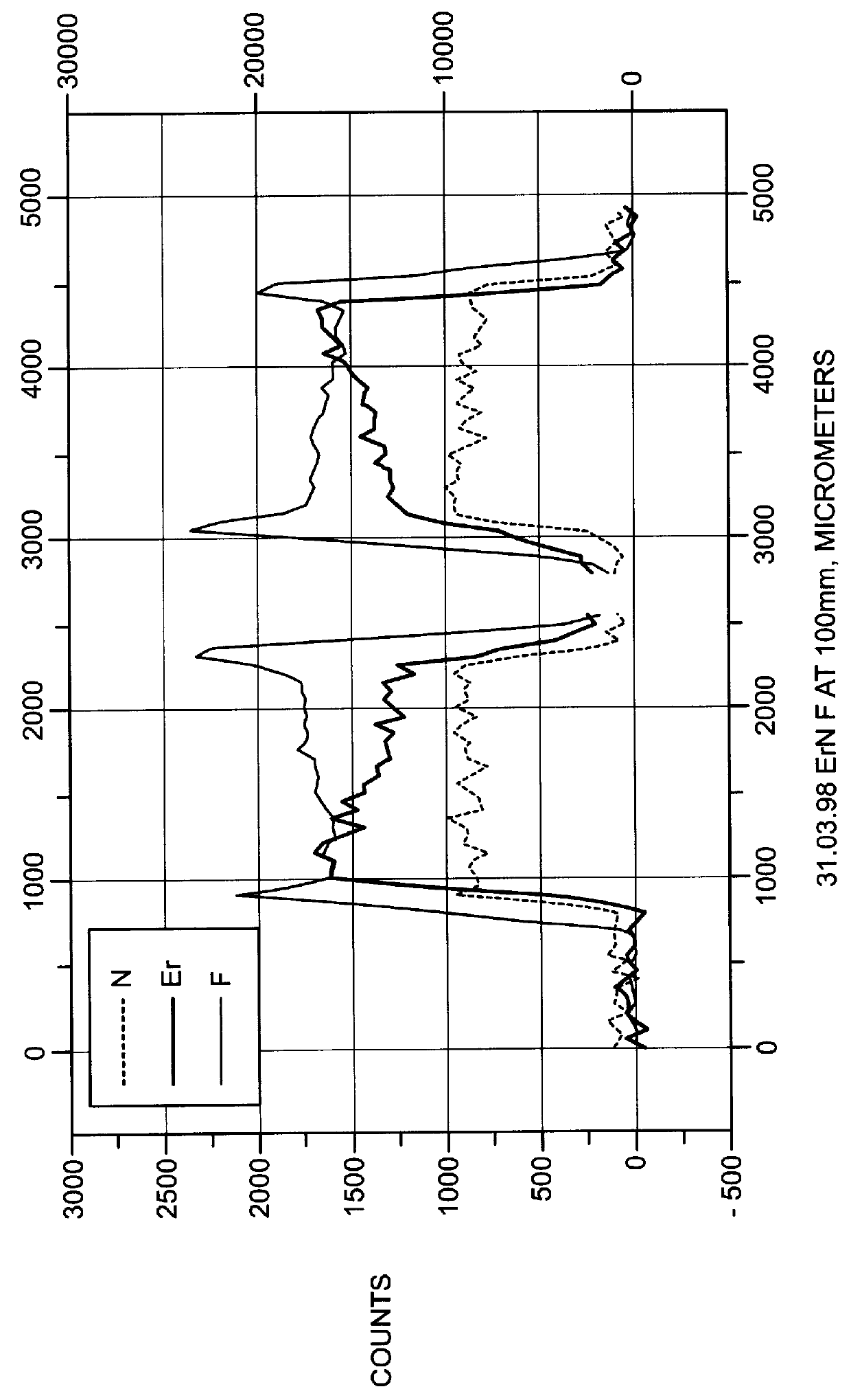
FIG. 2 shows that F, N and Er can be simultaneously doped into the preform. The N.sup.3- anion has a high charge that significantly alters the amplification characteristics. The combination of F and N also are beneficial since one F- and one N.sup.3- can substitute ...

example ii (

Prior Art)

Al.sub.2 O.sub.3 doping is currently used in Type II EDFA to both increase the Er.sub.3+ solubility and gain flatness over pure SiO.sub.2. However, these compositions can only yield a 40 nm band gain ripple of 30% and are prone to devitrification at high levels of Al.sub.2 O.sub.3, greater than a few wt %. The inventive glasses yield a 40 nm band gain ripple of less than 20% and are therefor more desirable for multichannel EDFA's.

Fluoride glasses such as ZBLAN (53ZrF.sub.4 -20BaF.sub.2 -4LaF.sub.3 -3AlF.sub.3 -20NaF in mole %) are also known for their gain flatness and low phonon energy. They must be pumped at 1480 nm due to upconversion, and as a result of the 1480 pumping, they have increased noise. They also are extremely difficult to fiberize, are not fusion sliceable, are prone to devitrification and have poor durability.

These glasses provide a means for producing low-loss rare earth doped fiber with improved gain flatness for increased channel capacity. Fiber produce...


PUM

PropertyMeasurementUnit
weight percentaaaaaaaaaa
wavelengthaaaaaaaaaa
FWHMaaaaaaaaaa

Abstract

These glasses incorporate a combination of F and Al2O3 to achieve even wider fluorescence and improved gain flatness. In addition, SPCVD incorporates large amounts of N into low-loss fiber whose high charge has an impact on rare earth behavior. The Surface Plasma Chemical Vapor Deposition (SPCVD) produces fiber preforms with high levels of F, Al2O3, and N. These heavily fluorinated glasses provide much broader Er3+ emission than Type I or Type II silica for enhanced multichannel amplifiers. SPCVD successfully fluorinates silica with losses below 5 dB/km and increased Er3+ emission width.

Description

This invention relates to fluorinated and nitrided silicate glasses made by Surface Plasma Chemical Vapor Deposition. The new glasses are useful for gain flattened Er.sup.3+ fiber amplifiers.Er.sup.3+ doped fiber amplifiers have revolutionized optical telecommunications by providing all-optical high-gain, low-noise amplification without the need for costly electronic repeaters. However, current amplifiers are not well suited for multichannel amplification due to the strong dependence of their gain as a function of wavelength. The fluorinated aluminosilicate glasses provide superior gain flatness in the 1530-1560 nm wavelength band over type I and type II silica. This enables simultaneous uniform amplification of multiple wavelengths for a 4-32.times. increase in bandwidth in both fiber and planar devices. This also makes high data rate communication systems practical and affordable. For example, 16 channels at 10 Gb / s (OC-192 Standard) for 160 Gb / s.sup.2 or even 32 channels at 2.4 g...

Claims


Application Information

Patent Timeline
Patent Type & Authority Patents(United States)
IPC IPC(8): C03C4/12C03C3/112C03C13/00C03C4/00C03C3/06C03C3/062C03C13/04C03C3/076G02B6/00C03C3/23C03C3/253H01S3/06H01S3/17
CPCC03C3/06C03C3/062C03C13/046C03C4/0071C03C4/12C03C3/112
Inventor DEJNEKA, MATTHEW J.KHRAPKO, ROSTISLAV
Owner CORNING INC
Why Eureka
Try Eureka