Spring clip for attaching an electronic component to a heat sink and an assembly utilizing the same

a technology of electronic components and spring clips, which is applied in the direction of cooling/ventilation/heating modifications, semiconductor/solid-state device details, power transistors and processors, etc., can solve the problems of the opposite end of the thermal field being lifted upward and out of the thermal field, generating significant amounts of heat which must be dissipated, and affecting the heat dissipation

Inactive Publication Date: 2000-06-27
AAVID THERMALLOY LLV +1
View PDF25 Cites 42 Cited by
  • Summary
  • Abstract
  • Description
  • Claims
  • Application Information

AI Technical Summary

Benefits of technology

Another object of the invention is to provide a spring clip which may be used with heat sinks of different sizes, shapes and thicknesses and does not require the extrusion of special mounting features in the heat sink.
It is a further object of the invention to provide a spring clip which produces higher normal forces, a greater range of deflection to accommodate a variety of electronic component packages over a full range of thickness tolerances and is capable of sustaining a greater stress prior to plastic deformation than spring clips of the prior art.
Still another object of the invention is to provide a spring clip which substantially reduces or prevents excessive rotation under load when used with heat sinks having relatively thin mounting walls.

Problems solved by technology

Electronic components secured to circuit boards, as for example power transistors and processors, generate significant amounts of heat which must be dissipated for the components to operate reliably.
These conventional arrangements present significant disadvantages.
First, mounting holes in electronic components are not typically located in the center of the component and thus, the compressive force imparted to one end of the component by the mounting hardware often causes the opposite end to lift upwards and out of thermal contact with the heat sink.
Second, the installation and removal of separate hardware is time consuming and not readily performed automatically using machines, thereby increasing the labor and manufacturing costs.
Finally, the trend in the electronic industry has been to eliminate mounting holes in component packages thereby rendering traditional hardware impracticable or obsolete.
Aluminum, however, does not exhibit mechanical properties sufficient to maintain deflection forces over time at increased temperatures and the condition on stamping relatively small sizes limits the applicability of such design.
This alternative configuration, however, does not solve the mechanical problems associated with manufacturing the spring clip using aluminum and requires an additional manufacturing step that increases the overall cost.
These clips are made from steel and thus overcome the mechanical problems associated with aluminum but have limited applicability in that the steel clips are only suitable for use with specific heat sinks.
Although not limited to use with specific heat sinks, this spring clip configuration sacrifices spring width for the retention features resulting in relatively large extreme fiber stresses at the union of the bayonet arms to the main body of the spring clip.
Thus, such spring clips are limited in the amount of force and range of deflection which may be achieved prior to plastic deformation.
Another disadvantage of this particular design is the inability to mount components to opposite surfaces of a heat sink utilizing the same mounting features.
This configuration overcomes the stress problems associated with bayonet type designs but are prone to excessive rotation under load due to manufacturing and design tolerances, and thus are limited to use with relatively thick walled heat sinks.
Moreover, this construction is extremely sensitive to variations in wall thickness and slot tolerances.
In addition, the horizontal orientation of the mounting slots impedes the conduction of heat from the device area below the mounting slots to the finned area above the mounting slots thereby increasing the thermal resistance of the heat sink.

Method used


Image

  • Spring clip for attaching an electronic component to a heat sink and an assembly utilizing the same
  • Spring clip for attaching an electronic component to a heat sink and an assembly utilizing the same
  • Spring clip for attaching an electronic component to a heat sink and an assembly utilizing the same

Examples


Embodiment Construction

The terms "device", "electronic component", "component", and "electronic component package" are synonymous and used interchangeably throughout the description of the invention.

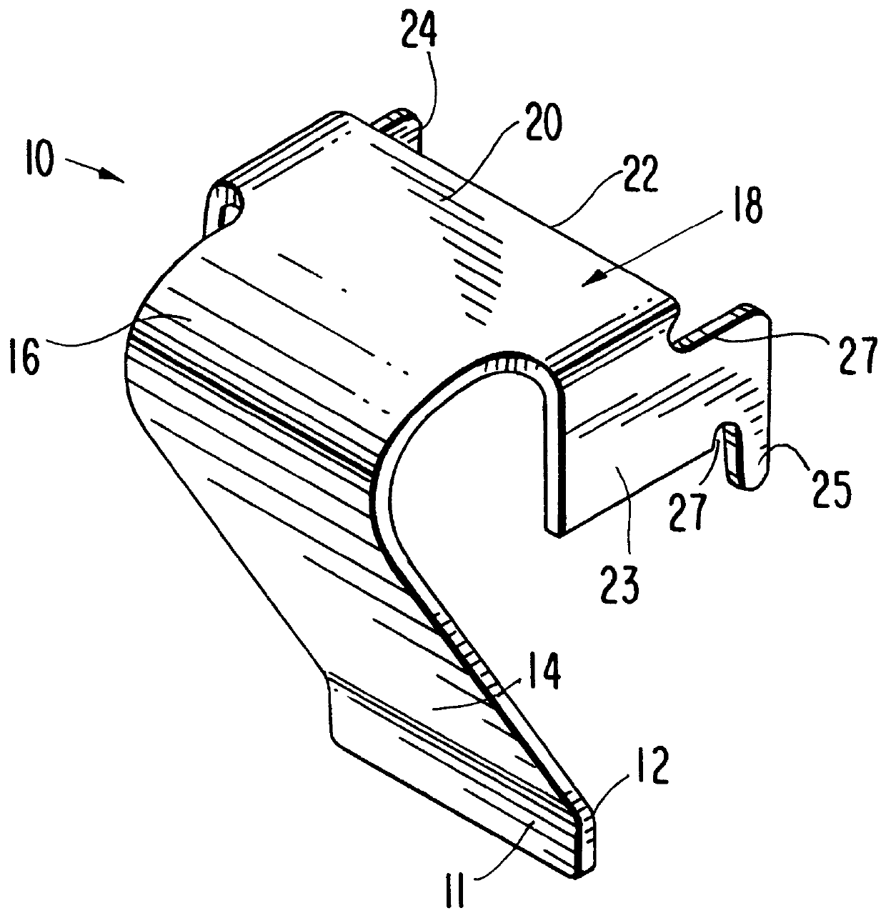
FIG. 1 shows a spring clip in accordance with the present invention. The spring clip 10 comprises a contact region 12 adapted to contact an electronic component (not shown) and translate a spring force to the electronic component when the spring clip 10 is in an engaged condition. On one side of the contact region 12 the spring clip 10 terminates in a lip 11 and on the opposite side of the contact region 12 a cantilever 14 extends upward to a bend 16. On the opposite side of the bend 16 is a mounting region 18 having a substantially planar upper surface 20 that terminates in an engaging edge 22. Two outriggers 23, 24 project substantially perpendicularly from opposite sides of the upper surface 20 of the mounting region 18 and downwardly towards the contact region 12 and beyond the engaging edge 22. In the pre...


PUM


Abstract

A spring clip manufactured from a single piece of metal for attaching an electronic component to a heat sink for defining a heat dissipation assembly. The spring clip comprises a main body having a bend with a cantilever on one side of the bend and a mounting region terminating in an engaging edge on the other side of the bend. Outriggers project perpendicularly from both sides of the mounting region and extend beyond the engaging edge In the assembly outriggers project through slots in the heat sink and the electronic component is secured between one side of the heat sink and the engaging edge of the spring clip. The outriggers preferably include retaining members which abut the opposite side of the heat sink thereby resisting rotation of the spring clip relative to the heat sink.

Description

1. Field of the InventionThe present invention is directed to heat sinks and in particular to a spring clip for applying a compressive force between an electronic component and a heat sink.2. Description of the Related ArtElectronic components secured to circuit boards, as for example power transistors and processors, generate significant amounts of heat which must be dissipated for the components to operate reliably. Some of the heat can be dissipated through the leads of the components. Much of the excess heat, however, is released into the ambient air. It is known in the art that cooling of such electronic components can be improved by thermally coupling the component to a finned or pinned heat sink.Traditionally, electronic components are mounted to heat sinks by passing bolts through holes defined in the heat sink and the component and securing the bolts with separate nuts. In other configurations, the heat sinks employ tapped holes or threaded fasteners pressed into the heat s...

Claims


Application Information

Patent Timeline
Patent Type & Authority Patents(United States)
IPC IPC(8): H01L23/34H01L23/40
CPCH01L23/4093H01L2924/0002H01L2924/00
Inventor CENNAMO, JOHNMANDELL, KEITH T.
Owner AAVID THERMALLOY LLV
Why Eureka
Try Eureka