Milling tool having cassette-mounted inserts attached to a rotary supporting body

a technology of supporting body and insert, which is applied in the field of milling tools, can solve the problems of increasing reducing the number of cutting inserts that can be mounted on the periphery of the supporting body, and reducing the efficiency of the milling tool as a whole, so as to facilitate mounting and dismounting work, increase the machining speed, and reduce the weight of the supporting body

Inactive Publication Date: 2000-07-11
SANDVIK INTELLECTUAL PROPERTY AB
View PDF14 Cites 37 Cited by
  • Summary
  • Abstract
  • Description
  • Claims
  • Application Information

AI Technical Summary

Benefits of technology

A primary object of the invention is thus to create a milling tool that can be equipped with a large number of cutting inserts for a given diameter, with the ultimate object of making an increased machining speed possible.
A further object is to provide a milling tool having a supporting body that, when needed, may be manufacture...

Problems solved by technology

This means that the number of cutting inserts that can be mounted upon the periphery of the supporting body is restricted in an unsatisfactory way.
However, a disadvantage in connection with steel is that this material has a relatively high density.
This means, due to the fact that the supporting body constitutes the major part of the entire volume of the milling tool, that the milling tool as a whole becomes heavy.
A consequence of a heavy weight of the tool is that the machining spee...

Method used


Image

  • Milling tool having cassette-mounted inserts attached to a rotary supporting body
  • Milling tool having cassette-mounted inserts attached to a rotary supporting body
  • Milling tool having cassette-mounted inserts attached to a rotary supporting body

Examples


Embodiment Construction

As will be apparent from the foregoing description, the present invention uses means that enables a quick and simple fine adjustment of the cutting inserts in both the axial and the radial directions.

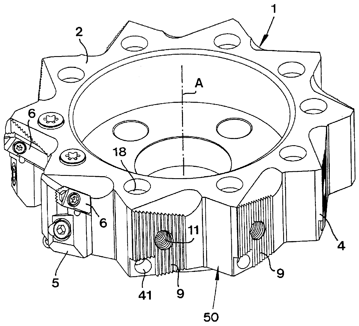
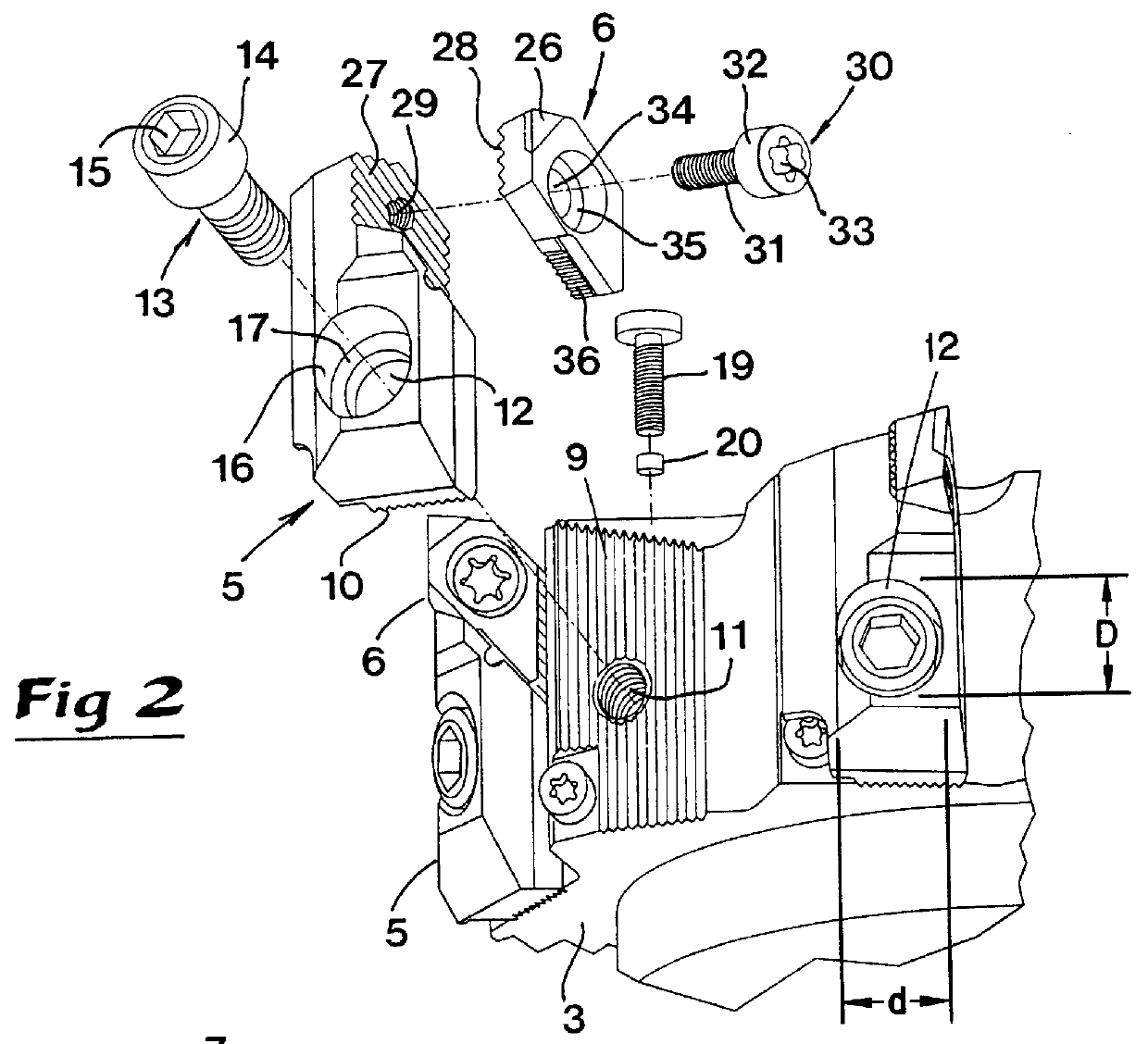
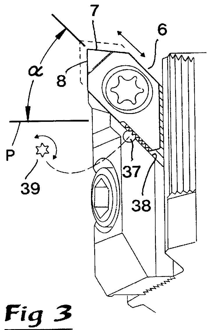
The milling tool illustrated in FIGS. 1-4 comprises a supporting body 1 that is rotatable around a central geometrical axis A, said supporting body 1 having a cylindrical basic shape (said supporting body often also being designated as a milling cutter head). Between opposite, planar end surfaces 2, 3 (see both FIGS. 1 and 2) there is an endless, circumferential peripheral face 4 which does not constitute a cylindric or smooth face, but rather has the character of an envelope surface. Upon said envelope face or circumferential face 4 several cassettes 5 are provided. Each cassette 5 supports in turn a cutting insert 6. The cutting is performed according to the embodiment by a corner cutter and consequently each cutting insert 6 includes two cutting edges 7, 8 which form the corner. The ...


PUM


Abstract

A milling tool includes a rotatable supporting body having detachable cassettes upon which cutting inserts are mounted. The cutting inserts are provided with cutting edges. Two serrated surfaces are provided in order to connect the individual cassette with the supporting body. A first of the two serrated surfaces is located upon the periphery of the supporting body and faces outwards from the supporting body, while the other serrated surface is formed at an inner side of the cassette.

Description

The present invention relates to a milling tool comprising a supporting body rotatable around a central geometric axis, said supporting body having an endless circumferential surface which extends between opposite end surfaces, several mutually separated cassettes being detachably mounted upon said circumferential surface, each cassette including a detachable cutting insert having two cutting edges.PRIOR ARTA milling tool of the type defined above is previously known from Werner et al. U.S. Pat. No. 6,529,439. Similar milling tools, using wedge bodies for clamping of the cutting inserts, are previously known from U.S. Pat. Nos. 2,037,642, U.S. Pat. No. 3,214,825 and U.S. Pat. No. 3,501,822. Common for all these known tools is that the cutting inserts are accommodated in and project from radial grooves or recesses that open in the circumferential surface of the supporting body.It should be possible to adjust all of the cutting inserts of a milling tool in very precise working positio...

Claims


Application Information

Patent Timeline
IPC IPC(8): B23C5/24B23C5/16B23C5/08
CPCB23C5/241B23C5/2479B23C5/2496Y10T407/1916Y10T407/1918Y10T407/193Y10T407/1934B23C5/24B23C5/2226
Inventor QVARTH, INGEMARENQUIST, LARS-ERIK
Owner SANDVIK INTELLECTUAL PROPERTY AB
Why Eureka
Try Eureka