Method and apparatus for diagnosing and controlling rotating stall and surge in rotating machinery

a technology of rotating machinery and surge, which is applied in adaptive control, digital computer details, instruments, etc., can solve the problems of reducing the capability of discharge head, affecting the discharge head, and causing damage labyrinths between

Inactive Publication Date: 2000-07-18
BENTLY NEVADA CORP
View PDF12 Cites 64 Cited by
  • Summary
  • Abstract
  • Description
  • Claims
  • Application Information

AI Technical Summary

Benefits of technology

Accordingly, a primary object of the instant invention is to provide a new, novel and useful method and apparatus for diagnosing and correcting rotating stall and surge effects in rotating machinery.

Problems solved by technology

Rotating stall and surge are important machine phenomena which can lead to dangerous machine damage in rotating machines such as a compressor as a result of a plurality of reasons.
First, rotor vibrations resulting from the stream line degradation can damage labyrinths between stages.
In addition, flow reversals can cause continuous increase in temperature at impeller vane entrances (and a corresponding decrease in discharge head capability), resulting in surge cycling.
Also, pressure variations between intake and discharge ends of the compressor can cause rapid changes in axial thrust, thereby risking damage to the thrust bearing.
Furthermore, abrupt load and speed changes may occur thereby detrimentally affecting the impellers and other internal compressor and driver components.
The rate of gas flow is not enough to adequately fill the spaces between consecutive guide vanes.
Therefore, even though aerodynamically the rotating stall phenomena has been investigated extensively, the rotor dynamic implications of this phenomena has received little attention.

Method used


Image

  • Method and apparatus for diagnosing and controlling rotating stall and surge in rotating machinery
  • Method and apparatus for diagnosing and controlling rotating stall and surge in rotating machinery
  • Method and apparatus for diagnosing and controlling rotating stall and surge in rotating machinery

Examples


Embodiment Construction

Considering the drawings, wherein like reference numerals denote like parts throughout the various drawing figures, reference numeral 10 is directed to the apparatus and method according to the instant invention.

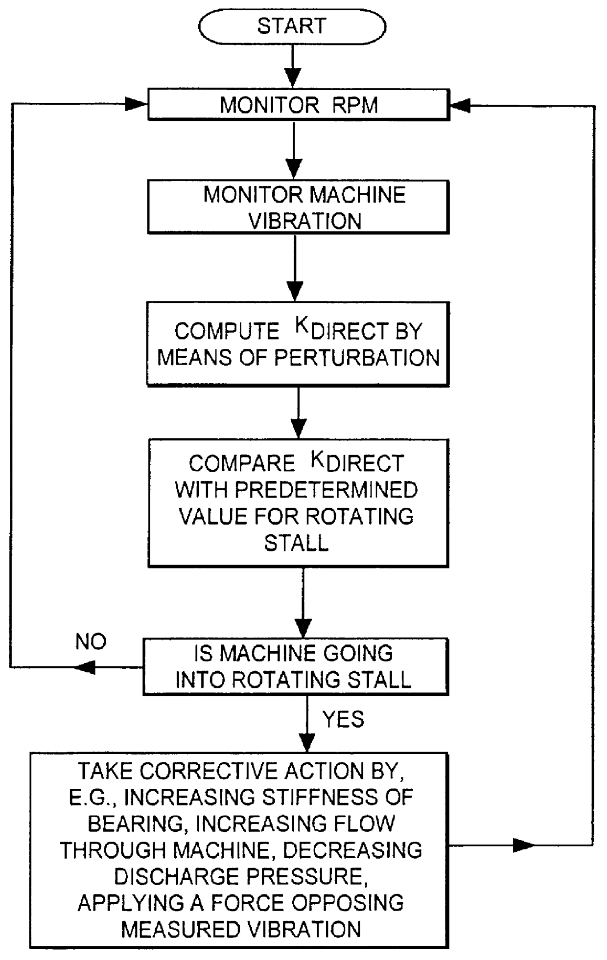
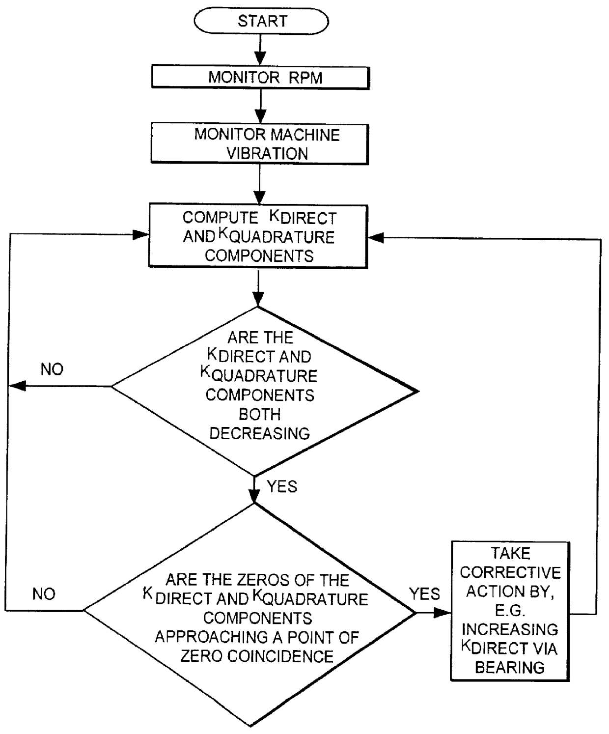
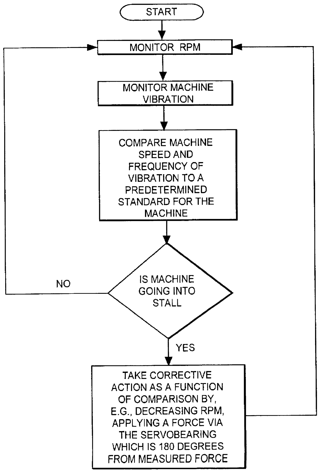
In its essence and referring to the drawing figures, the instant invention provides a method and apparatus for diagnosing and correcting destabilizing effects in rotating machines by measuring the dynamic stiffness of the machine and computing the direct dynamic stiffness and / or the quadrature dynamic stiffness for use as an instability warning device and also for diagnosing and correcting rotor dynamic destabilizing effects. Corrective action is taken correlative to the diagnosed anomalies and these actions can take the form of, inter alia, increasing the stiffness of the bearing, increasing the flow through the machine M, decreasing the discharge pressure and / or applying a force causing a response opposing measured machine vibration.

The instant invention preferably include...


PUM


Abstract

A method and apparatus is provided for diagnosing and correcting rotating stall and surge in rotating machines by monitoring dynamic shaft precession and comparing this precession with a standard and altering the precession as the machine approaches a destabilizing condition when indicated by the comparison step. Axial vibration monitoring means is also provided for monitoring and comparing a dynamic axial vibration of the machine with a standard and altering the axial vibration as the machine approaches a destabilizing condition. Furthermore, the instant invention measures the complex dynamic stiffness of the machine and computes the direct dynamic stiffness and the quadrature dynamic stiffness for use as a destabilizing warning device by monitoring for a drop in direct dynamic stiffness and/or a coincidence of zero crossing of both the direct dynamic stiffness and the quadrature dynamic stiffness components. One embodiment for altering the rotating stall and/or surge is by a controlled active servobearing.

Description

The instant invention relates generally to machinery having a rotating stage, such as a compressor or pump and, more particularly, to machinery subject to operating anomalies known as rotating stall and surge and to a method and apparatus for diagnosing and controlling the occurrence of such stall and surge anomalies from a rotor dynamic viewpoint.Rotating stall and surge are important machine phenomena which can lead to dangerous machine damage in rotating machines such as a compressor as a result of a plurality of reasons. First, rotor vibrations resulting from the stream line degradation can damage labyrinths between stages. In addition, flow reversals can cause continuous increase in temperature at impeller vane entrances (and a corresponding decrease in discharge head capability), resulting in surge cycling. Also, pressure variations between intake and discharge ends of the compressor can cause rapid changes in axial thrust, thereby risking damage to the thrust bearing. Further...

Claims


Application Information

Patent Timeline
Patent Type & Authority Patents(United States)
IPC IPC(8): F04D27/02G01M13/04
CPCF04D27/02G01M13/045
Inventor BENTLY, DONALD E.
Owner BENTLY NEVADA CORP
Why Eureka
Try Eureka