Apparatus for and methods of implanting desired chemical species in semiconductor substrates

Inactive Publication Date: 2000-07-25
APPLIED MATERIALS INC
View PDF10 Cites 70 Cited by
  • Summary
  • Abstract
  • Description
  • Claims
  • Application Information

AI Technical Summary

Problems solved by technology

In addition, problems can arise due to cross contamination whereby species from a previous implantation run contaminate surfaces of the target chamber and are subsequently deposited onto a substrate during a later implantation run with another species.
A particular problem of this kind arises when arsenic is implanted after a previous phosphorus implantation.
Problems can also arise from any carbon contamination.
The presence of carbon contamination on the substrate surface during subsequent implant

Method used


Image

  • Apparatus for and methods of implanting desired chemical species in semiconductor substrates

Examples


Example

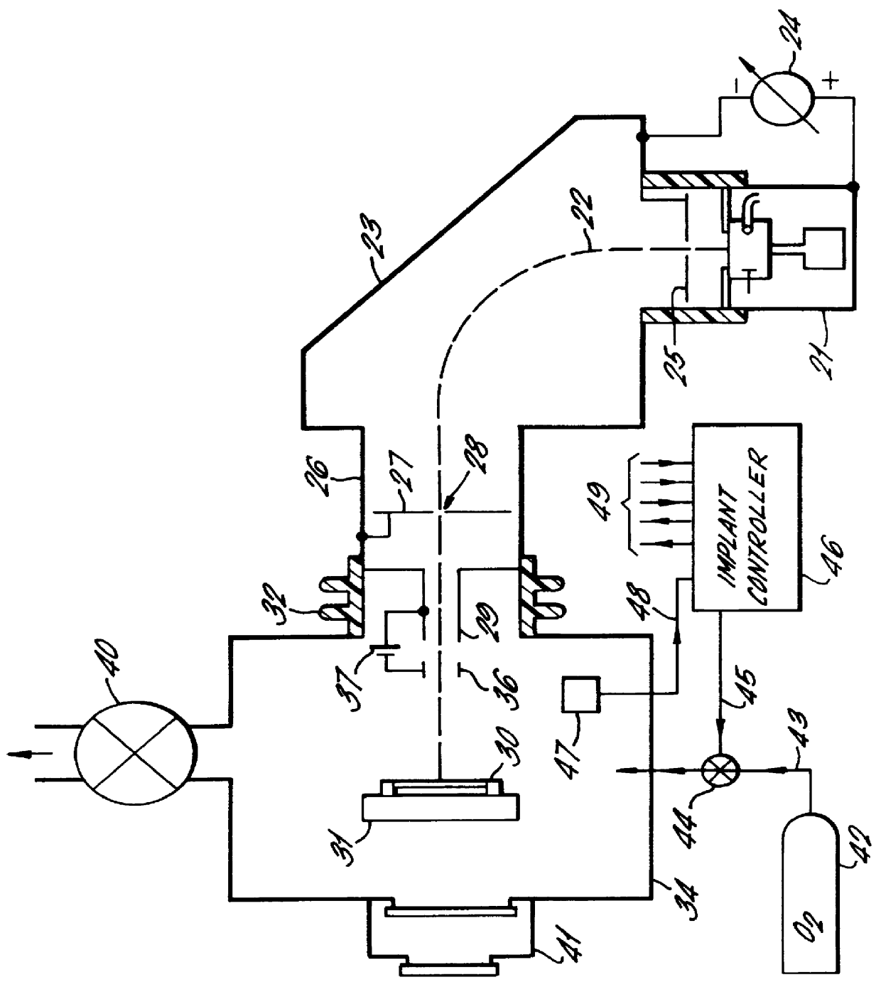
In the drawing, an ion implanter comprises an ion source 21 from which a beam 22 of ions are extracted. The ion source 21 is mounted by insulators on the structure of a mass selection magnet 23. An extraction bias 24 biases the ion source relative to an extraction electrode 25 at the entrance to the mass selection magnet 23. The mass selection magnet 23 causes the ions in the beam 22 to travel in a curved path so that ions of the desired mass / charge ratio are focused at an electrode 27. Only ions of the desired mass / charge ratio pass through a mass selection slit 28 in the electrode 27 and hence continue along a linear beam path to impinge on the surface of a wafer 30 held in a holder 31 in the target chamber 34 of the implanter. The target chamber 34 is itself mounted by means of an insulator 32 on a flight tube 26.

The target chamber 34 is pumped down by a vacuum pump 40 and maintained at a low pressure suitable for implantation. Generally, the substrate 30 on its holder 31 is main...


PUM


Abstract

An apparatus and method for implanting a desired chemical species in a semiconductor substrate. The apparatus comprises a target chamber, a holder to hold a substrate in the target chamber for implantation, a pump to pump the target chamber down to a desired pressure, a pressure lock to enable a substrate to be passed into the target chamber for loading on the holder while the target chamber is at sub-atmospheric pressure, an ion beam generator for generating and directing a beam of ions containing said desired species at a surface of a substrate on said holder, and a reactive gas supply to feed a reactive gas into the target chamber while the chamber is maintained by the pump at the desired pressure, to provide a desired partial pressure of the reactive gas in the target chamber to reactive with and volatilise unwanted contaminants on surfaces in the target chamber.

Description

The present invention is concerned with implanting desired chemical species in semiconductor substrates, particularly using a beam of ions containing the desired species.DISCUSSION OF THE PRIOR ARTIon implantation is a well established technology used for introducing desired levels of dopant species into surface and subsurface layers of a semiconductor substrate. Although this technology is well established and refined to a considerable degree, there is continuing pressure on the technology to improve performance, e.g. by forming thinner and shallower layers (using low energy ions), and to reduce contamination of the substrate by unwanted chemical species.Ion implantation is conducted in an evacuated chamber containing the substrate to be implanted. An ion beam containing the desired species and at the desired implant energy is directed at the substrate. Contamination of the substrate can arise from the presence of other substances in the atmosphere in the target chamber of the impl...

Claims


Application Information

Patent Timeline
IPC IPC(8): H01J37/317H01L21/265
CPCH01J37/3171H01J2237/006H01J2237/022
Inventor WAGNER, DENNIS W.WAUK, II, MICHAEL T.CASTLE, MATTHEW D. SCOTNEYADIBI, BABAK
Owner APPLIED MATERIALS INC
Why Eureka
Try Eureka