Wavelength router

a router and wavelength technology, applied in the field of multi-wavelength optical switches, can solve the problem of not increasing the integration size of the router

Inactive Publication Date: 2000-08-01
LAPIS SEMICON CO LTD
View PDF0 Cites 22 Cited by
  • Summary
  • Abstract
  • Description
  • Claims
  • Application Information

AI Technical Summary

Problems solved by technology

Such a multiwavelength highway switch has a problem in that it cannot increase its integration size.

Method used


Image

  • Wavelength router
  • Wavelength router
  • Wavelength router

Examples


first embodiment

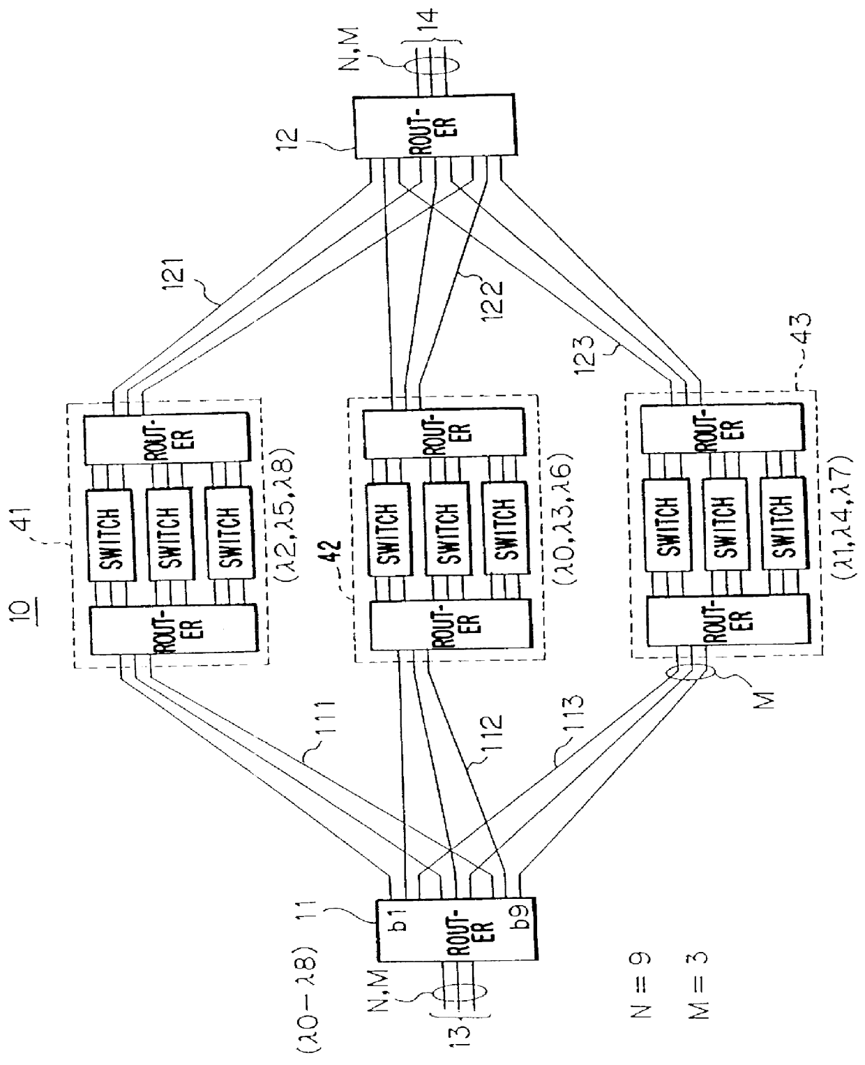
FIG. 1 is a schematic, functional block diagram showing a multiwavelength optical switch in accordance with the present invention. The multiwavelength optical switch system 10 comprises wavelength routers 11 and 12. The wavelength router 11 is connected to incoming paths 13 consisting of multiwavelength optical transmission lines, such as optical fibers, and the wavelength router 12 is connected to outgoing paths 14 also consisting of multiwavelength optical transmission lines, thereby forming a circuit switching system for connecting a desired wavelength channel of the incoming paths 13 to any desired one of the outgoing paths 14.

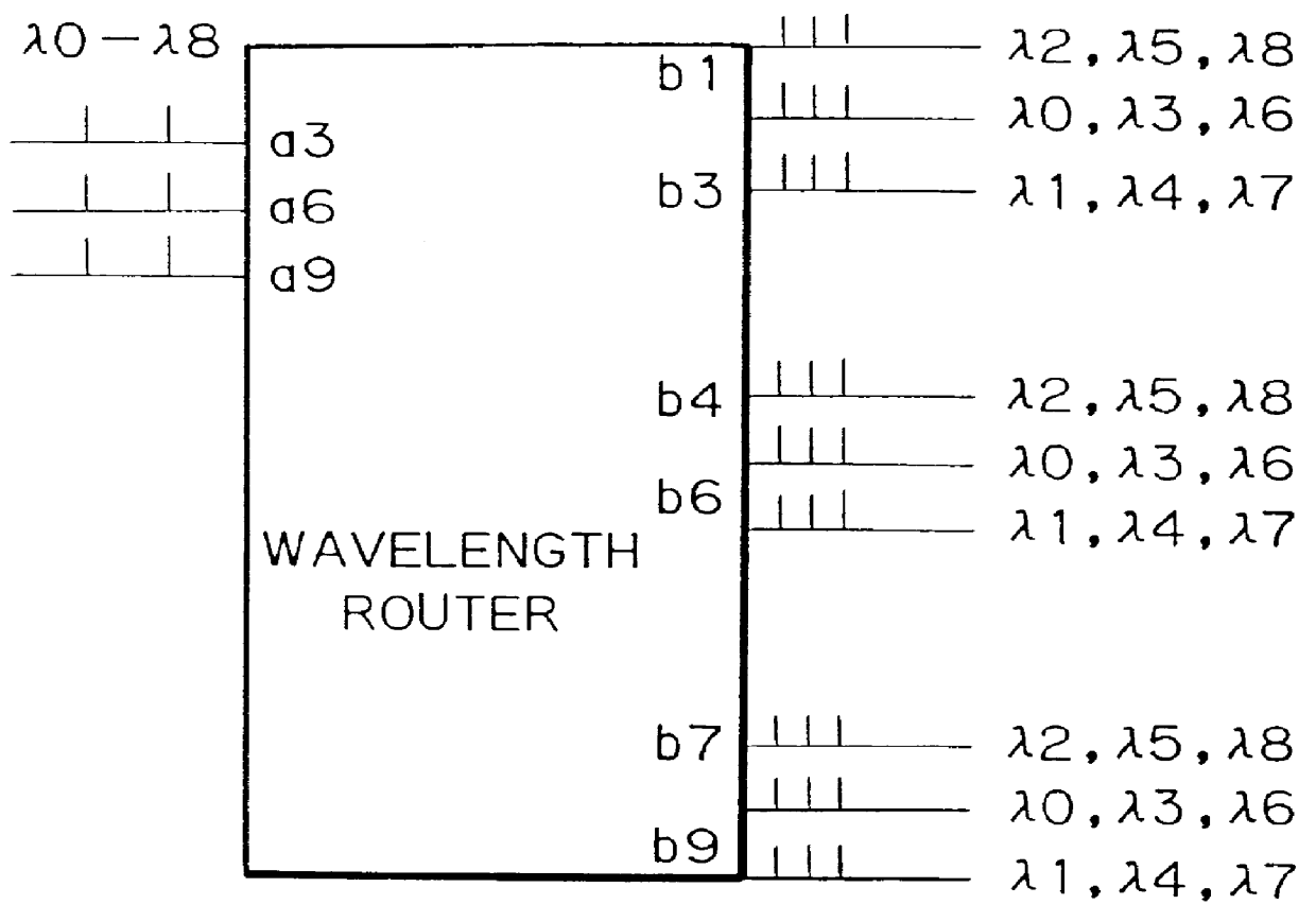
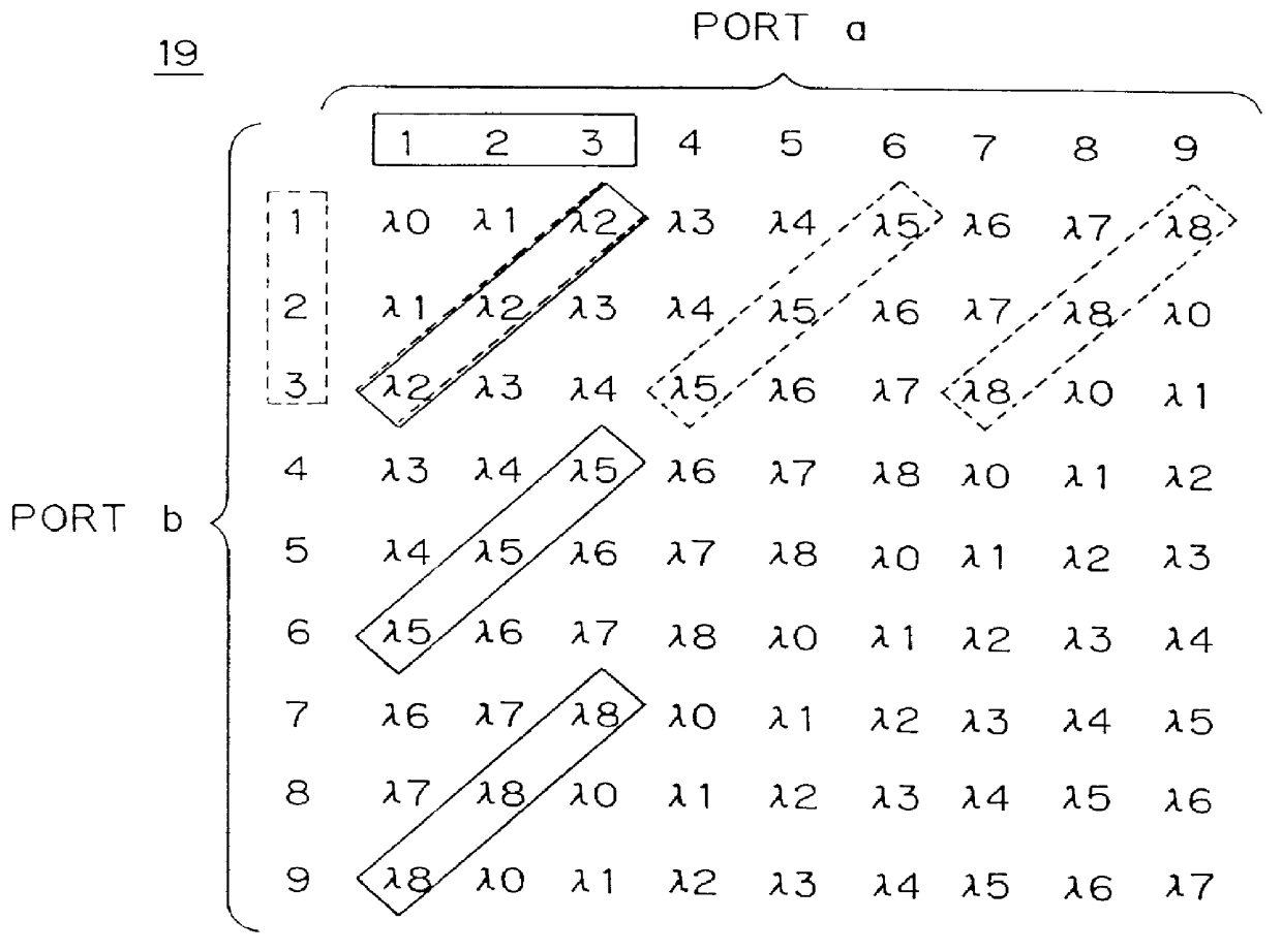
The wavelength routers 11 and 12 can have the same logic configuration as shown in FIG. 2. Each wavelength router has a port set a consisting of nine ports #1-#9, and a port set b consisting of nine ports #1-#9. The ports a1-a9 and b1-b9 have the wavelength selecting characteristics as shown in FIG. 2 in the form of a matrix 15. When an optical signal incl...

embodiment 2

FIG. 8 is a block diagram of a multiwavelength optical switch 50 as a second embodiment of the present invention. Wavelength routers 11a, 11b and 11c in the input stage, and wavelength routers 12a, 12b and 12c in the output stage can be of the same configuration as the wavelength routers 11 and 12 as shown in FIG. 3. The ports a3, a6 and a9 of these wavelength routers are connected to the incoming and outgoing paths 51 and 52 of optical signals consisting of 9 multiwavelengths f0-f8. Accordingly, each wavelength router of the input and output stages of this embodiment has the port number M=3, and the multiplexed number per port N=3, and the number of routers per stage L=3. The respective wavelength routers 11a, 11b and 11c output three sets of 3 multiwavelength signals (.lambda.2, .lambda.5, .lambda.8), (.lambda.0, .lambda.3, .lambda.6) and (.lambda.1, .lambda.4, .lambda.7) with the multiplexed number N / M being three, and supply them through a link 53 to multiwavelength optical swit...

embodiment 3

FIG. 10 is a block diagram of a multiwavelength optical switch 60 of a third embodiment in accordance with the present invention. The multiwavelength optical switch 60 is planarly formed on an optical distributing substrate 90, as shown in FIG. 11, with wavelength routing devices 61, 62 and 63 connected to incoming paths A1, A2 and A3, and to a wavelength router 64 connected to outgoing paths B1, B2 and B3.

FIG. 11 is a diagram showing a, particular structure of the wavelength routing devices 61, 62 and 63, each of which includes a plane waveguide 65 which outputs from each of optical paths 67 an optical multiwavelength signal including three wavelengths .lambda.0, .lambda.1 and .lambda.3 applied to an input port 66 connected to one of the incoming paths A1, A2 and A3, and supplies the optical multiwavelength signal to each one of multiwavelength selecting filters 68 consisting of an acousto-optic (AO) filter or the like. The multiwavelength selecting filters 68 each have their own p...


PUM


Abstract

A wavelength router has first ports each receiving or providing a first multiwavelength optical signal having wavelengths, and second ports each providing or receiving second multiwavelength optical signals having multiplexed wavelengths. The number of multiplexed wavelengths of the second multiwavelength optical signal is smaller than the number of wavelengths of the first multiwavelength optical signal. The first multiwavelength optical signal is demultiplexed into the second multiwavelength optical signal. The second multiwavelength optical signals are multiplexed into the first multiwavelength optical signal. The first multiwavelength optical signal has a number N of multiplexed wavelengths, and the second ports are divided into M sets of second ports. The first multiwavelength optical signal is demultiplexed into optical signals having a number N/M of multiplexed wavelengths, which are supplied to the M sets of second ports.

Description

1. Field of the InventionThe present invention relates to a multiwavelength optical switch connected to a plurality of multiwavelength optical circuits, such as optical fibers which transmit a multiwavelength optical signal, and for carrying out circuit switching across channels of the same wavelengths.2. Description of the Background ArtThe following conventional circuit switching systems are described in Ken-ichi Yukimatsu et al., "Introduction to Optical Switching Technique", pp. 42-43, Ohm Limited, 1993, Tokyo, one of the references on conventional multiwavelength optical signals.A first system demultiplexes a multiwavelength optical signal into a plurality of wavelengths with wavelength channel selectors provided for individual channels, and inputs the demultiplexed signals to an optical matrix switch for the individual channels, thereby outputting the signals from desired output ports. A second system splits a multiwavelength optical signal into signals which correspond in num...

Claims


Application Information

Patent Timeline
Patent Type & Authority Patents(United States)
IPC IPC(8): H04Q11/00
CPCH04Q11/0005H04Q2011/0016H04Q2011/0024H04Q2011/0032H04Q2011/0075
Inventor OKAYAMA, HIDEAKI
Owner LAPIS SEMICON CO LTD
Why Eureka
Try Eureka