Rotary grinder method and apparatus

a rotary grinder and grinder technology, applied in lighting and heating equipment, combustion types, borehole/well accessories, etc., can solve the problems of not teaching a structure for performing such adjustment nor a method, the disposal of drill cuttings from various types of wells is becoming increasingly difficult, and the disposal of all drill cuttings is not as convenien

Inactive Publication Date: 2000-08-15
RICKY & MARCELLE DAVENPORT REVOCABLE TRUST
View PDF1 Cites 41 Cited by
  • Summary
  • Abstract
  • Description
  • Claims
  • Application Information

AI Technical Summary

Problems solved by technology

However, the apparatus does not teach a structure for performing such adjustment nor does it teach a method for interchangeably adapting non-intermeshing rotor and stator elements.
For example, the disposal of drill cuttings from drilling various types of wells has become an increasingly difficult problem due to restrictions imposed by various governmental authorities and the desire to minimize environmental damage.
In many instances, however, disposal of all of the drill cuttings is not as conveniently handled.

Method used


Image

  • Rotary grinder method and apparatus
  • Rotary grinder method and apparatus
  • Rotary grinder method and apparatus

Examples


Embodiment Construction

In the description which follows, like parts are marked throughout the specification and drawing with the same reference numerals, respectively. The drawing figures are not necessarily to scale and certain features may be shown in schematic form in the interest of clarity and conciseness.

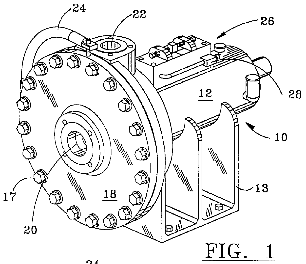
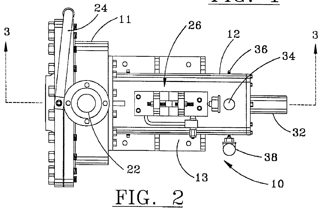
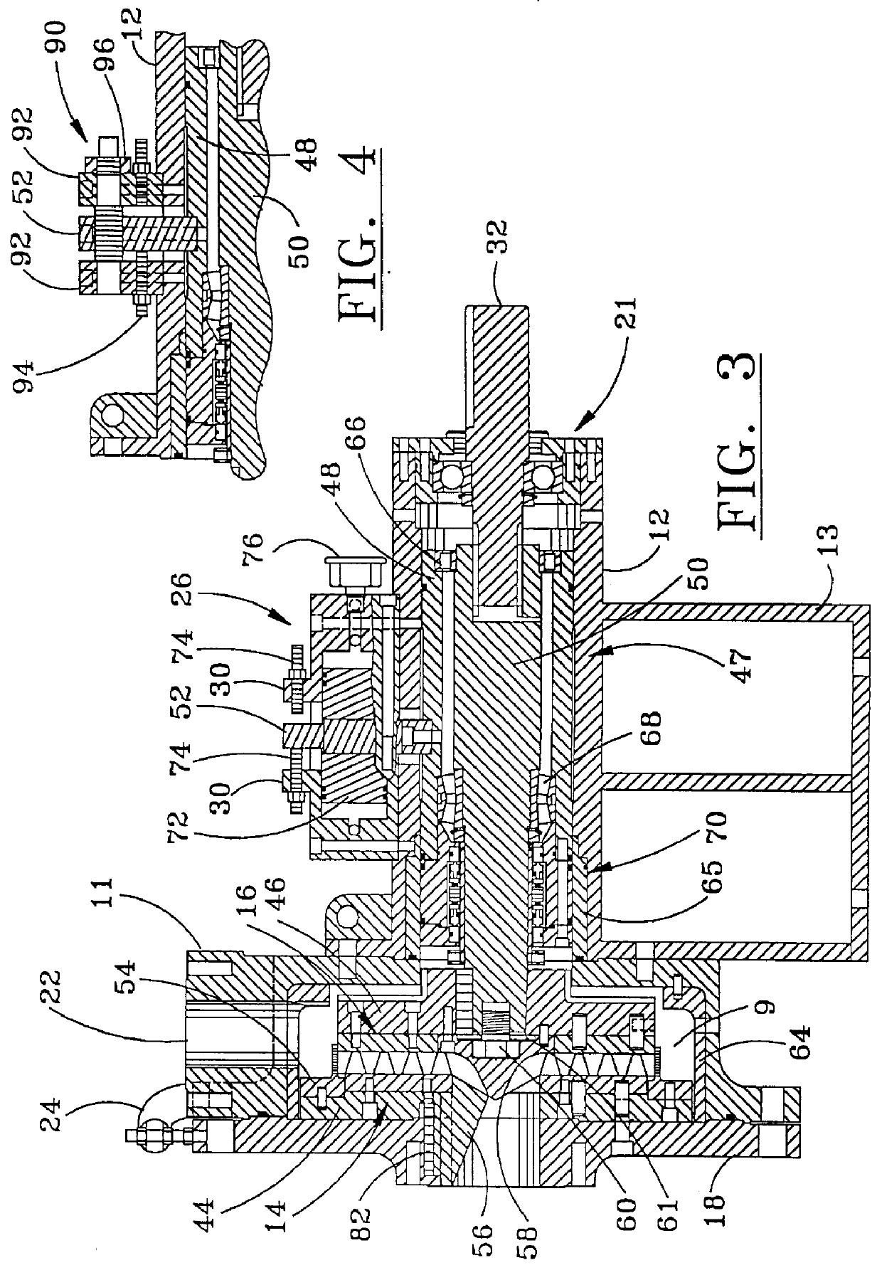
The in-line grinder 10 shown in FIG. 1 includes a casing 12 and a grinding chamber housing 1,1 better seen in FIG. 2, which houses the segmented stator and rotor assemblies 14,16 shown in FIGS. 5 and 6 and disclosed in the prior art or variations thereof illustrated in FIGS. 13-20, which collectively accomplish product size reduction as required. The casing 12 is generally supported by a mounting frame member or base portion 13. The stator / rotor assemblies are accessed through the removal of the casing cover 18 via bolts 17, which is supported by a pivot arm 24. The position of the rotor assembly 14 relative to the stator assembly 16 is adjusted through the use of a hydraulic actuator mechanism 26 l...


PUM

PropertyMeasurementUnit
Pressureaaaaaaaaaa
Massaaaaaaaaaa
Viscosityaaaaaaaaaa

Abstract

An in-line grinder has been developed which can be configured to perform in a variety of applications through the use of an adjustable rotor/stator assembly, removable shear bar, and a variety of interchangeable stator-rotor configurations. A unique drive system utilizing a mechanical seal cartridge provides maximum sealing with a minimum of shaft deflection and run-out, thereby improving performance. These improvements collectively allow the grinder to be configured for optimum sizing of solids to a predetermined particle size for a broad range of materials. It has been demonstrated that a class of in-line grinders such as that described herein is applicable for sizing drill cuttings for injection into a subsurface formation by way of an annular space formed in a wellbore. The cuttings are removed from the drilling fluid, conveyed to a shearing and grinding system that converts the cuttings into a viscous slurry with the addition of water and viscosity enhancing polymers. The system in its simplest form comprises a slurry tank, a pump, and the instant in-line grinder. The pump circulates the mixture of cuttings, water including sea water and chemicals between the slurry tank and the in-line grinder. The ground mixture leaving the in-line grinder is then routed to an injection pump for high pressure injection into the formation.

Description

1. Field of the InventionThe present invention relates to in-line grinding or milling apparatus in general which size and disperse solids contained in a liquid slurry as they are pumped through it and more particularly to machines with adjustable rotors having a number of stator-rotor combinations interchangeably mountable in the machine to accomplish a wide variety of size reduction needs. The present invention also pertains to the use of such in-line grinding apparatus in drill cuttings disposal systems wherein the cuttings2. General BackgroundIt is well known within the art that a stator-rotor assembly composed of intermeshing teeth or shear blocks may be use in the sizing of both flexible and friable solids. However, heretofore, fine grinding of such solids produced by such methods has been done by different machines, i.e. ball, or roller mills and fine shredders and the like.An apparatus for grinding solids as they are pumped through the machine has been disclosed in U.S. Pat. ...

Claims


Application Information

Patent Timeline
IPC IPC(8): B02C7/14B02C7/12B02C7/06B02C7/04B02C7/00E21B21/06D21B1/00D21B1/02D21B1/34E21B21/00E21B41/00B02C7/16B02C19/00F23G5/033
CPCB02C7/04B02C7/06B02C7/12B02C7/14B02C7/16B02C19/0056D21B1/026D21B1/345E21B21/066E21B41/0057F23G5/033F23G2201/603F23G2201/80
Inventor DAVENPORT, RICKY W.
Owner RICKY & MARCELLE DAVENPORT REVOCABLE TRUST
Why Eureka
Try Eureka