Surface acoustic wave filter with first and second filter tracks and balanced or unbalanced terminals

a surface acoustic wave and filter track technology, applied in the direction of impedence networks, electrical devices, etc., can solve the problems of small inferior group delay time characteristic, transversal type surface acoustic wave filter has large insertion loss and device siz

Inactive Publication Date: 2000-08-15
SKYWORKS PANASONIC FILTER SOLUTIONS JAPAN
View PDF16 Cites 43 Cited by
  • Summary
  • Abstract
  • Description
  • Claims
  • Application Information

AI Technical Summary

Problems solved by technology

The resonator type surface acoustic wave filter has narrow-band and steep cut-off characteristics, and also small insertion loss and device size, while being inferior in group delay time characteristic.
On the other hand, the transversal type surface acoustic wave filter has large insertion loss and device size, while having a broad-band and flat group delay time deviation characteristic.
This entails a problem that each length of the input and output IDTs is increased, which leads to a difficulty in miniaturization thereof.
Further, weighting results in a difference in configuration between the upper electrode and the lower electrode of the IDT electrode pair 152, which creates a problem of bad balancing.

Method used


Image

  • Surface acoustic wave filter with first and second filter tracks and balanced or unbalanced terminals
  • Surface acoustic wave filter with first and second filter tracks and balanced or unbalanced terminals
  • Surface acoustic wave filter with first and second filter tracks and balanced or unbalanced terminals

Examples


embodiment 1

(Embodiment 1)

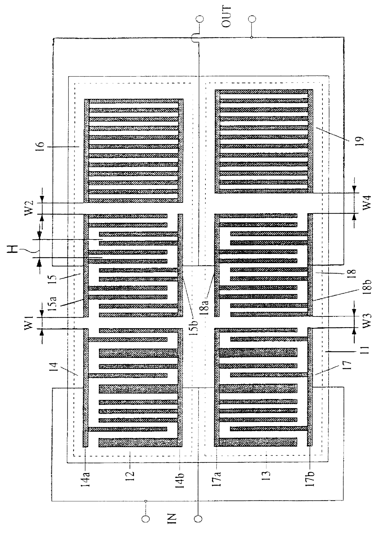
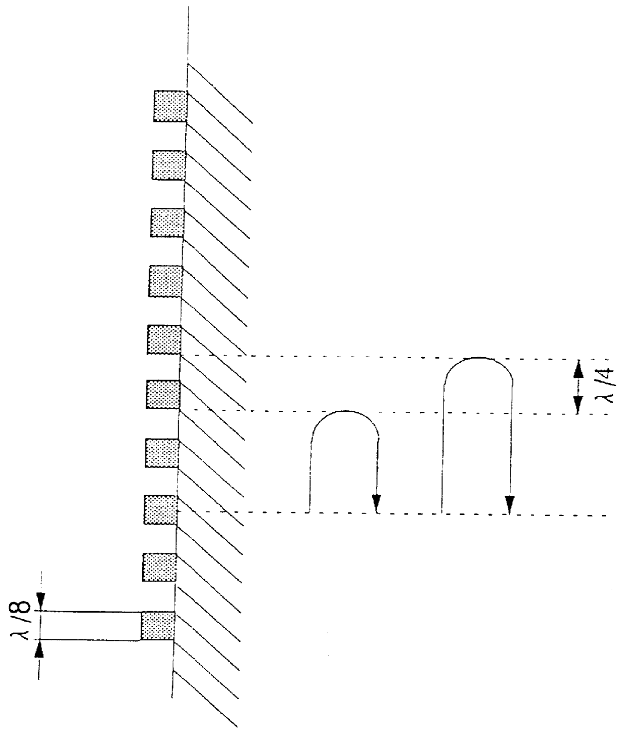
FIG. 1 is an electrode pattern block diagram showing a first embodiment of a surface acoustic wave filter according to the present invention. On a single crystal piezoelectric substrate 11 shown in FIG. 1, is formed an electrode pattern in stripline of a periodic structure, enabling the excitation of a surface acoustic wave. On the piezoelectric substrate 11, are formed a first filter track 12 and a second filter track 13. The first filter track 12 is comprised of an input IDT 14, an output IDT 15, and a reflector 16. Similarly, the second filter track13 is comprised of an input IDT 17, an output IDT 18, and a reflector 19. The distance W1 between the input IDT 14 and the output IDT 15 of the first filter track 12 is equal to the distance W3 between the input IDT 17 and the output IDT 18 of the second filter track 13. Assuming that the wavelength of the surface acoustic wave is .lambda., the distance W2 between the output IDT 15 and the reflector 16 of the first filter...

embodiment 2

(Embodiment 2)

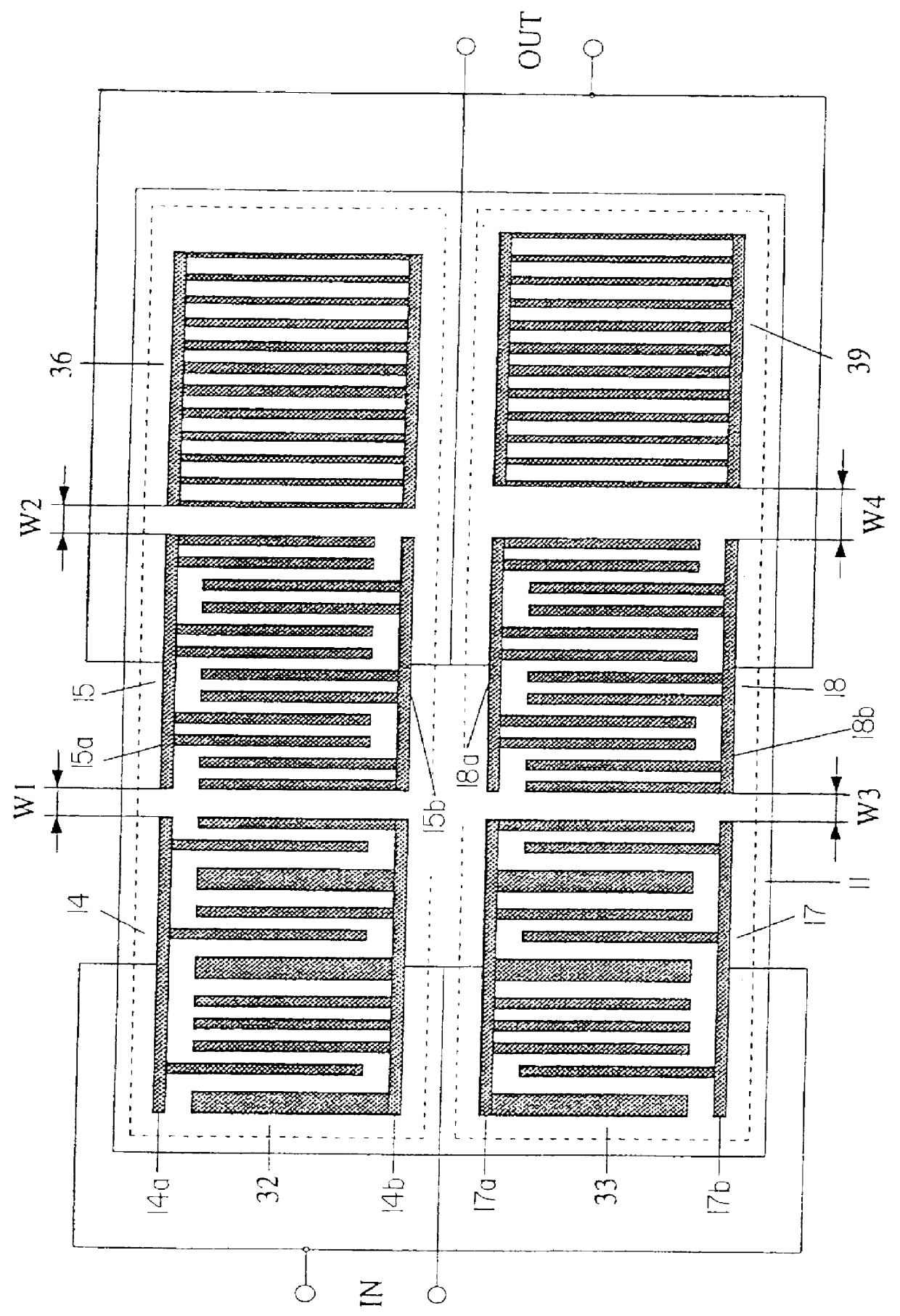
FIG. 3 is a block diagram of an electrode pattern showing a second embodiment in accordance with the present invention. The difference from the embodiment 1 shown in FIG. 1 is in that on each of a reflector 36 of a first filter track 32 and a reflector 39 of a second filter track 33, weighting based on the width along the surface acoustic wave propagation direction of the electrode finger is performed. This enables the expansion of the degree of freedom of filter design. Alternatively, weighting based on the position of the electrode finger, and weighting based on the combination of the foregoing two terms can be carried out.

FIG. 4 is a block diagram of an electrode pattern in which the reflector 36 of the first filter track 32 and the ref lector 39 of the second filter track 33 are each comprised of at least two or more reflectors each having a different reflection characteristic. Referring now to FIG. 4, a reflector 46 of a first filter track 42 is comprised of refle...

embodiment 3

(Embodiment 3)

FIG. 5 is a block diagram of an electrode pattern showing a third embodiment of the surface acoustic wave filter in accordance with the present invention. The difference from the embodiment 1 shown in FIG. 1 is as follows: in the embodiment 1, a connection is provided between the upper electrode 14a of the input IDT 14 of the first filter track 12 and the lower electrode 17b of the input IDT 17 of the second filter track 13 to form one of the balanced type input terminals. Meanwhile, a connection is provided between the lower electrode 14b of the input IDT 14 of the first filter track 12 and the upper electrode 17a of the input IDT 17 of the second filter track 13 to form the other of the balanced type input terminals. Thus, the balanced type input is implemented. On the other hand, in the embodiment 3 shown in FIG. 5, the upper electrode 54a of an input IDT 54 of a first filter track 52 and the lower electrode 57b of an input IDT 57 of a second filter track 53 form ba...


PUM


Abstract

A surface acoustic wave filter. The filter includes two filter tracks which are parallel to each other. Each track has an input interdigital transducer, reflector and output interdigital transducer. This distance between the input transducer and output transducer is the same in both tracks. The distance between the output transducer and reflector is different in the two tracks. The electrical connection is in opposite phase in either the inputs or outputs, but not both. Electrode fingers are arranged in groups of two and have widths and spacings related to the wavelength.

Description

1. Field of the InventionThe present invention relates to a surface acoustic wave filter for use in, for example, high-frequency circuits in radio communication devices.2. Related Art of the InventionThe electromechanical components using a surface acoustic wave have received attention in the tide toward higher density of hardware due to the following fact, that is, the acoustic velocity of the wave is several km / s, and the energy of the wave has a property of concentrating on the surface of a propagation medium. Also, with the advance of thin film forming technology and surface processing technology which have enabled the development of an interdigital transducer (below, referred to as IDT) electrode, and the transformation and expansion thereof, they have been applied to practical use for radar delay lines and band-pass filters for television receivers. At present, they have come in wide use as filters of RF and IF stages in transmitter-receiver circuits of radio communication dev...

Claims


Application Information

Patent Timeline
Patent Type & Authority Patents(United States)
IPC IPC(8): H03H9/00H03H9/64H03H9/02H03H9/145
CPCH03H9/0042H03H9/6433H03H9/6453H03H9/0285H03H9/14505H03H9/14526H03H9/643
Inventor YAMADA, TORUTSUZUKI, SHIGERUNAKAMURA, HIROYUKI
Owner SKYWORKS PANASONIC FILTER SOLUTIONS JAPAN
Why Eureka
Try Eureka