Power supply apparatus for reduction of power consumption

a power supply apparatus and power supply technology, applied in emergency power supply arrangements, process and machine control, instruments, etc., can solve the problems of waste of power, no load loss, waste of power,

Inactive Publication Date: 2000-08-15
FIDELIX
View PDF3 Cites 84 Cited by
  • Summary
  • Abstract
  • Description
  • Claims
  • Application Information

AI Technical Summary

Problems solved by technology

Therefore, either appliances always consume some electrical power for watching and waiting for a signal even when the main units of the appliances do not work.
Therefore, in order to keep the standby function, a certain amount of electrical power is always being consumed in these appliances.
Therefore, as long as the equipment is connected to a commercial AC power supply, some wasted power, so-called "no-load loss", is always consumed in the AC adapter.
However, even if such an auxiliary power supply is provided, it is still not sufficient to save energy.
Because, the apparatus, which should always be operated even when the main unit is in a standby mode, is required to be always in an electrically conductive condition, and thus a significant amount of electrical power is consumed in the apparatus.
In the case, particularly, the power supply apparatus is arranged as a switching regulator, that a switching loss caused by the operation of a switching element is generated in addition to the copper loss and the iron loss.
As stated above, however, the problem of the electrical power consumption during when the main unit is in a standby mode is not only for the DC-DC converter but also for the AC-DC converter which uses a commercial AC supply.
If the technique disclosed in the above publication is applied to the AC-DC convert

Method used


Image

  • Power supply apparatus for reduction of power consumption
  • Power supply apparatus for reduction of power consumption
  • Power supply apparatus for reduction of power consumption

Examples


first embodiment

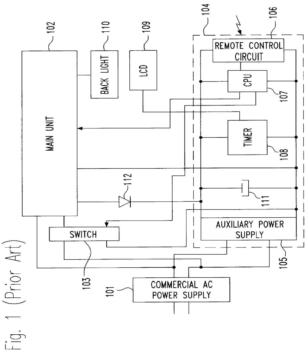
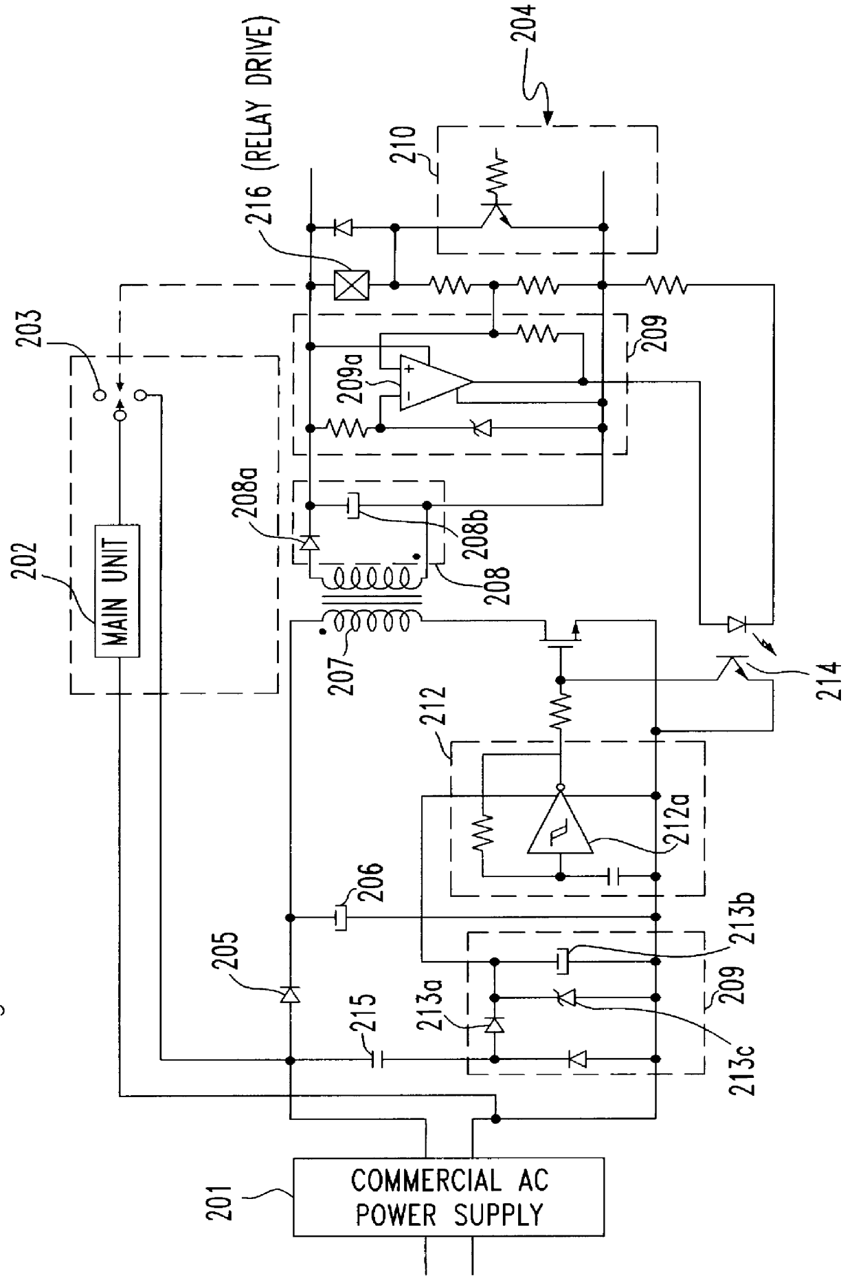
FIG. 2 is a circuit diagram showing a construction of a power supply apparatus according to the present invention. The apparatus of this embodiment is designed as a switching regulator, and is applied as an auxiliary power supply apparatus of an electrical appliance having a remote control system, which always consumes some electrical power even when the main unit of the appliance is in a standby mode. As shown in FIG. 2, the apparatus is constructed such that only when a switch 203 provided between the main unit 202 and a commercial AC power supply 201 is switched on in response to a signal from a remote control signal receiving circuit 210 which receives a remote control signal 204 from the outside, an electrical current is directly supplied to the main unit 202 from the commercial AC power supply 201. The main unit 202 comprises a main power supply (not shown) for supplying voltage and current for conducting the functions of the main unit 202.

The auxiliary power supply apparatus ...

second embodiment

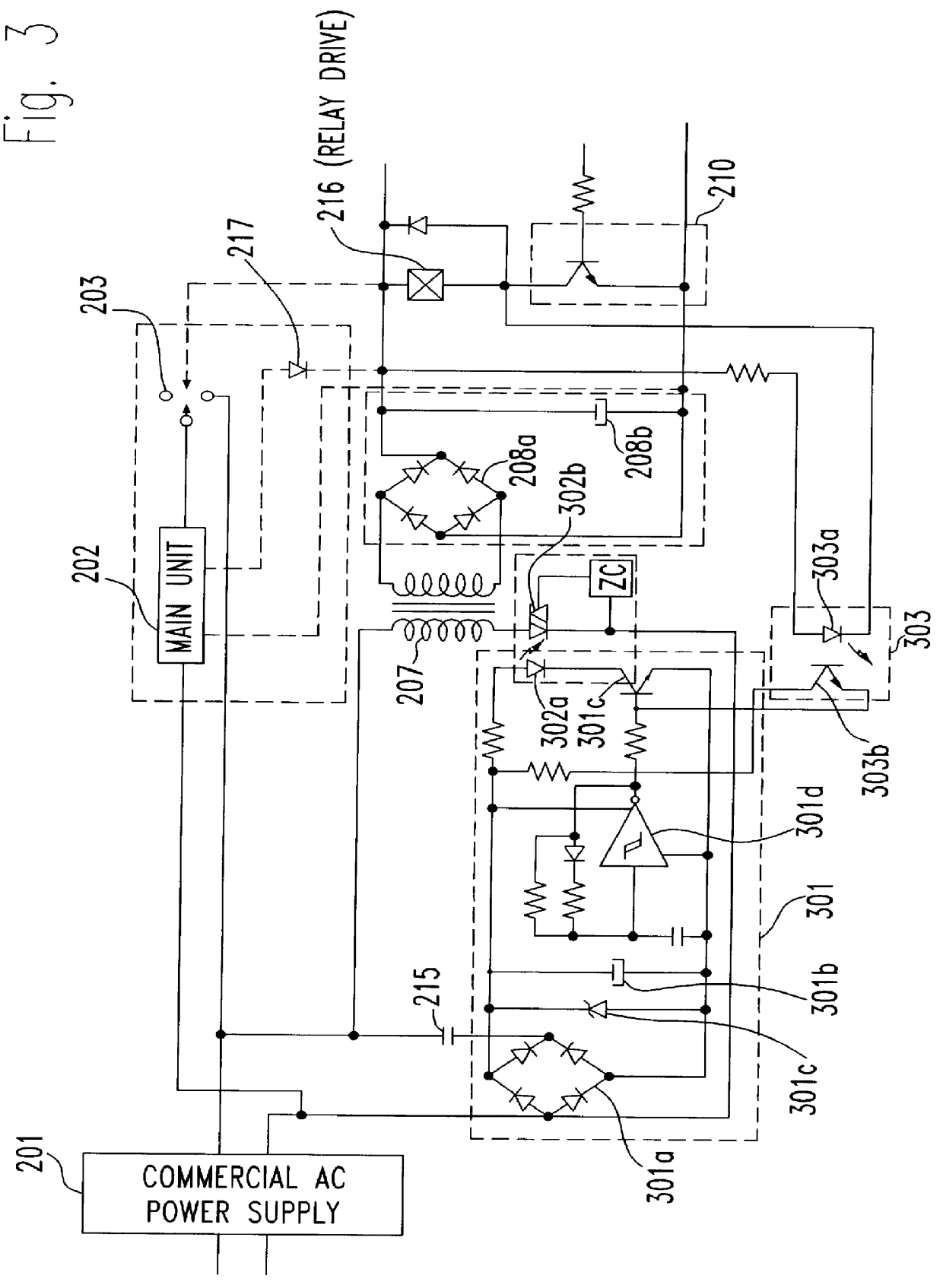
In the second embodiment, a switching device (a photo coupler) 302 is provided on an electrical current supply line from a commercial AC power supply 201 to the primary coil of the transformer 207; the switching device 302 is arranged so as to be operated intermittently in response to a load current of the auxiliary power supply apparatus, so that the amount of current supply to the primary coil of the transformer 207 can be reduced.

The electrical current supplied from the commercial alternative AC power supply 201 is sent to the transformer 207, while, supplied to a control circuit 301 for controlling the switching operation of the photo coupler 302. The same as the first embodiment, there is provided a capacitor 215 between the control circuit 301 and the commercial AC power supply 201, so that the control circuit 301 is operated by an electrical current going through a reactance component of the capacitor 215. Therefore, no energy loss is caused there because no initiating resist...

third embodiment

According to such an arrangement that an inductive impedance, i.e. a transformer, is driven after the input voltage is divided by the capacitor, a kind of impedance matching circuit is realized. Therefore, in case the power supply apparatus is applied as an auxiliary power supply in the appliance which is necessary to be driven even when the appliance is in a standby mode, the same transformer can be used for the other commercial AC power supplies having a different voltage supply by only changing a circuit constant. In the auxiliary power supply apparatus which is exclusively used for the apparatus which should always wait signals, it is possible to take a sufficient voltage from the secondary side of the transformer to drive the remote control circuit, etc. even the input voltage is divided, because the load of the auxiliary power supply apparatus is not so great.

FIG. 5 is a circuit diagram representing a power supply apparatus according to the fourth embodiment of the present in...


PUM


Abstract

A power supply apparatus having an AC power supply, a transformer, a switching element and a control circuit for controlling an operation of the switching element: where an electrical current is supplied to the primary side of the transformer intermittently when a main unit of an electrical appliance to which the power supply apparatus is applied is in a standby mode so that unnecessary power consumption is reduced. Further, a capacitance is provided between the AC power supply and the control circuit instead of the conventional initializing resistance and the control circuit is driven using an electrical current going through a reactance component of the capacitor, so that the energy loss is not caused any more by the initializing resistance.

Description

1) Field of the InventionThe present invention relates to a power supply apparatus, and particularly, relates to apparatuses where electrical power consumption can be greatly reduced. The power supply apparatus according to the invention can be suitably applied to any electrical appliance having a remote controlling system, such as television equipment, video equipment, audio equipment and air conditioning systems; electrical appliances where a sub-switch is provided to change the operational mode between a standby mode and a driving mode; electrical appliances, which should keep them in their standby mode even when the main functions of the appliance are not being used, such as telephone equipment, facsimile equipment and personal computers; or electrical appliances, such as modems and printers, which are designed such that electrical power is supplied through AC adapters.2) Related Prior ArtsA remote controlling system is used in many kinds of electrical appliances, due to its con...

Claims


Application Information

Patent Timeline
IPC IPC(8): H02M3/335H02M3/24H02M7/155H02J9/00H02M7/12
CPCH02J9/005H02M3/33523H02M7/1557H02M2001/0006H02M2001/0032Y02B70/16Y02B70/10Y04S20/20Y02B70/30H02M1/0006H02M1/0032H02M7/05
Inventor SHIN, NAKAGAWA
Owner FIDELIX
Why Eureka
Try Eureka