Fixing device for an image forming apparatus and fixing roller for the same

Inactive Publication Date: 2000-08-29
RICOH KK
View PDF14 Cites 57 Cited by
  • Summary
  • Abstract
  • Description
  • Claims
  • Application Information

AI Technical Summary

Problems solved by technology

A problem with such an indirect heating type of heat roller is that the heat source cannot beat the roller to the fixing temperature in a short period of time.
Another problem is that the heat roller cannot be held at the fixing temperature without increasing power consumption.
However, even the direct heating type of heat roller is disadvantageous in that only a limited range of materials are applicable to the roller, in that there is a fear of fire ascribable to unusual temperature elevation, in that the roller is apt to bend with respect to the axis thereof or to collapse in the radial direction, and in that the roller is not durable.
However, several hundred watts of power necessary for the fixing device of electrophotography is not achievable without increasing the size, weight and cost of the apparatus.
The problem with this approach is that because heat is generated along the wiring pattern, it is difficult to cause the heating body to heat uniformly over its entire surface.
Moreover, when the heating body and the base of the heat roller are formed of ceramics or sintered body whose thermal conductively is low, the amount of heat is irregular unless irregularities in the thickness and resistance of the heating body or layer are reduced.
It is therefore extremely difficult to set the resistance of the carbon fibers when it comes to an actual heating body.
This cannot be done without resorting to an expensive power source device.
Another problem with the heating pipe is that the heating body is positioned inside of the metallic pipe, increasing the temperature elevation time.
However, the amount of heat generated by the heating body is irregular so far as the disclosure indicates.
The irregular heat directly translates into irregular surface temperature on the heat roller, obstructing sufficient fixation of toner on a sheet.
Further, Laid-Open Publication No. 5-278141 does not teach whether or not the heating pipe can implement a heat roller capable of setting up a uniform temperature distribution.
Presumably, therefore, it is difficult to use the heating pipe as a heat roller.
In addition, it appears that an expensive power source device is indispensable in order to adjust the voltage to be applied to the heating body, as stated earlier.
However, because the heat from the lamp 14 is applied to the sheet S not directly, but by way of t

Method used


Image

  • Fixing device for an image forming apparatus and fixing roller for the same
  • Fixing device for an image forming apparatus and fixing roller for the same
  • Fixing device for an image forming apparatus and fixing roller for the same

Examples


second embodiment

The heat roller 54 of the second embodiment, FIG. 8, is applicable to a fixing device, as follows. In the heat roller 54, the base 1 is formed of aluminum and has a diameter of 30 mm, a length of 360 mm, and a wall thickness of 0.5 mm. The electrical insulating layer 1a formed of imide resin covers the inner periphery of the base 1. The heating layer 2 of carbon fibers covers the inner periphery of the insulating layer 1a. The annular electrodes 56 are implemented as copper tapes which are 5 mm wide each. The heating layer 2 is provided with a resistance of 12.5 .OMEGA. implementing the power consumption of 800 W at 180.degree. C. when 100 V is applied. This resistance is selected by taking account of a margin of 10.degree. C. with respect to a set temperature of 170.degree. C. The parting layer 3 covers the outer periphery of the heat roller 54. The bearings are formed of conventional fluorine-contained resin whose heat resisting temperature is 230.degree. C. The press roller 58, F...

fourth embodiment

the present invention will be described hereinafter. While the foregoing embodiments have paid attention to the thermal conductivity of the heating body, the fourth embodiment pays attention to the thermal conductivity of the metallic base. In addition, the fourth embodiment takes account of the modulus of elasticity because the base must be rigid against the pressure of fixation. In the embodiment to be described, the base formed of aluminum is provided with a wall thickness t corresponding to 0.5 mm and calculated on the basis of the modulus of elasticity.

The heat capacity of the base determining the temperature elevation time of the heat roller is produced by specific heat x density x thickness (t). Table 5 which will appear is respresentative of this embodiment. In Table 5, specific gravity available with the aluminum base is assumed to be "1" while heat capacities of bases formed of different materials are indicated in relative value. Because heat resistance is considered to ef...

fifth embodiment

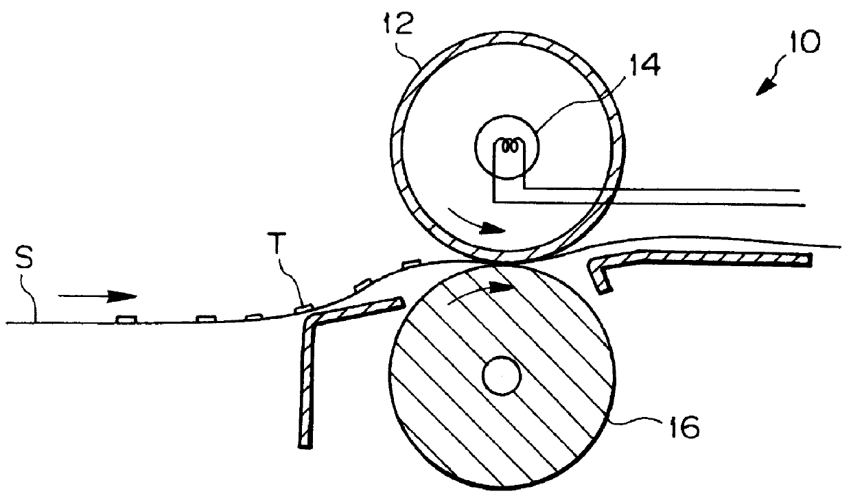
Referring to FIG. 24, the present invention will be described. As shown, a fixing device 80 includes a heat roller 86 and a press roller 88 located at both sides of guides 82 and 84. The press roller 88 is pressed against the heat roller 86 by a spring or similar biasing member, not shown. A cover 90 accommodates a temperature sensor 92, a cleaner 94, and a sheet separator 96 in addition to the heat roller 86. A spring 98 is anchored at one end to the cover 90 and at the other end to the sheet separator 96. The sheet separator 96 is rotatable about a shaft 100 and capable of separating a sheet S from the heat roller 96. While the sheet S carrying toner T thereon is pressed by the heat roller 86 and press roller 88, the toner T is melted by heat and pressure and fixed on the sheet S thereby. It is to be noted that the mechanism surrounding the heat roller 86 and press roller 88 is only illustrative.

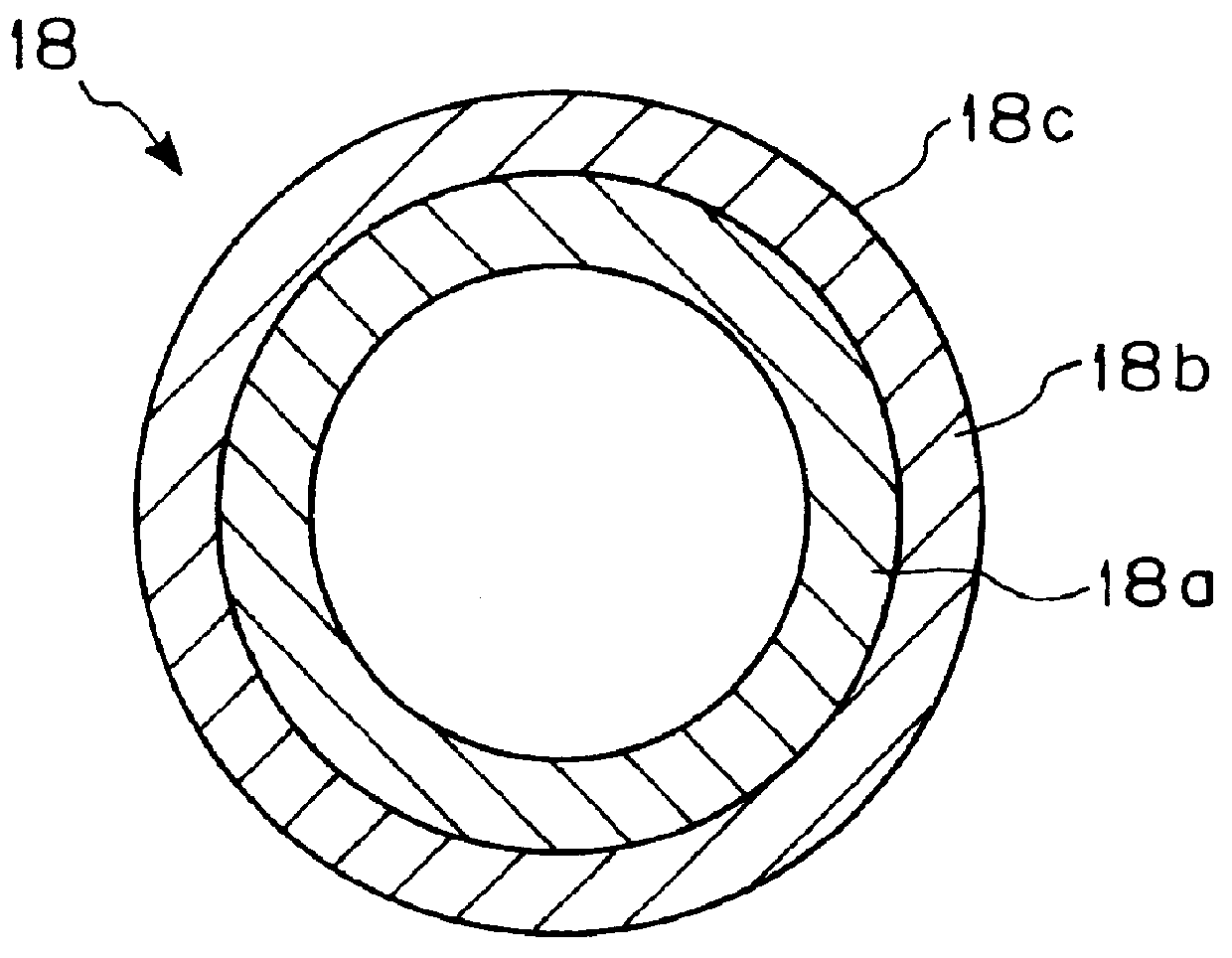
As shown in FIGS. 25A and 25B, the heat roller 86 is made up of a hollow cylindrical b...


PUM

PropertyMeasurementUnit
Timeaaaaaaaaaa
Timeaaaaaaaaaa
Lengthaaaaaaaaaa

Abstract

In a fixing device for an image forming apparatus, a heat roller includes a hollow cylindrical base, a heating layer formed of strip-like fibers implementing desired power consumption, and a parting layer provided on the outer periphery of the heating layer with the intermediary of an electrical insulating layer. The strip-like fibers of the heating layer are wound on the base and provided with a preselected resistance.

Description

1. Field of the InventionThe present invention relates to a fixing device for use in an electrophotographic apparatus, copier, facsimile apparatus or similar image forming apparatus, and a heat roller for the fixing device. More particularly, the present invention is concerned with a fixing device exhibiting a uniform temperature distribution, saving power, resistive to deflection and collapse, and safely operable, and a method of producing a heat roller for the same.2. Discussion of the BackgroundAn image forming apparatus of the kind described has a fixing device in which a press roller is held in pressing contact with a heat roller. While the heat roller heated is in rotation, the roller nips a sheet carrying toner thereon between it and the press roller. As a result, the toner is melted and fixed on the sheet. The current trend in the imaging art is toward an image forming apparatus with a power saving configuration. To save power, it is desirable that a heater accommodated in t...

Claims


Application Information

Patent Timeline
IPC IPC(8): G03G15/20H05B3/00
CPCG03G15/2053H05B3/0095Y10T29/49551
Inventor FUJITA, TAKASHIWADA, HIROSHINAKAMURA, SHIGEHARU
Owner RICOH KK
Why Eureka
Try Eureka