Dual evaporator for indoor units and method therefor

a technology of evaporator and indoor unit, which is applied in the direction of refrigeration components, lighting and heating apparatus, heating types, etc., can solve the problems of not paying particular attention to the variations, the actual refrigeration cycle may deviate from the ideal cycle, and the drawbacks of known evaporators

Inactive Publication Date: 2000-09-12
OLIVE TREE PATENTS 1 +1
View PDF29 Cites 70 Cited by
  • Summary
  • Abstract
  • Description
  • Claims
  • Application Information

AI Technical Summary

Benefits of technology

Simply, the coldest refrigerant passing through the thermal transfer cycle flows through the second (or more) or downstream evaporator section while the warmest refrigerant flows through the first or upstream evaporator section. The configuration of the present invention, providing a fist pass of air past the warmer evaporator section(s) precools the air supply before the air supply hits the colder downstream evaporator section(s) resulting in increased superheat temperatures and / or increased refrigerant mass flow out of the first evaporator section and, therefore, increased enthalpy and capacity. The increase in superheating of the refrigerants with the present invention may be up to 15 degrees Fahrenheit above standard superheat temperatures. Therefore, for every degree of increased superheating, there is a resulting increase in cooling capacity of the system. Also refrigerant mass flow will be increased, which contributes even more to increasing the cooling capacity of the system.
Moreover, the present invention may be configured such that wasted air space in the evaporators as a result of insufficient air flow across the evaporators is virtually eliminated. This problem may be solved by removing the squared corners of the evaporators; thereby creating contoured cut-out shaped corner portions, which decreases the area of lost refrigeration. Thus, the evaporators become more efficient and require a lower air flow. Because of the reduction in the fan speed necessary for adequate air flow, the efficiency of the refrigeration system increases as a result of the decrease in the input wattage to the fan. Thus, the Energy Efficiency Ratio (EER) increases because of the reduction in the necessary fan speed as well as the increased mass flow and / or increased superheat of the refrigerant because of the secondary (or more) contact(s) of the refrigerant with the same air supply through the dual (or multi) sectional evaporator system of the present invention. Moreover, utilizing the evaporators with contoured cut-out shaped corner portions decreases the space the evaporator will take up.
Furthermore, each of the evaporator sections of the present invention may have their inner coil configured in a particular manner as a result of the contoured cut-out shaped corner portions. Basically, evaporators are comprised of a plurality of serpentine rows extending from the bottom to the top of the evaporator. Each row of the coil within each evaporator should be of equal length. Simply, where the evaporator of the present invention comprises of contoured cut-out shaped corner portions, a serpentine row extends from the bottom of the evaporator on one side of the evaporator and then crosses over to the opposite side of the evaporator in order to reach the top of the evaporator. Typically, however, the center row of the coil of the present invention may extend upward without crossing over because the center of the evaporator is the average length of the evaporator. Therefore, a row of the coil may cross over another adjacent row in order to equal out its length because it may be able to extend further because the evaporator may be longer on the opposite side of the evaporator. On the other hand, where a row is particularly long, it may cross over to an opposite side, which is respectively shorter. Therefore, because of the decreased space and the configuration of the coils in adapting to the decrease in space, the fan speed can be reduced while maintaining and even increasing superheating and / or mass flow.
An important feature of the present invention is that the wasted air surface, because of insufficient air flow to the squared corner ends of the evaporators, has been reduced. Therefore, it can be readily seen that the present invention provides a means to decrease the area of lost refrigeration as well as decrease the space the evaporator takes up. Thus, an evaporator such as the present invention that is capable of increasing the latent heat removal and total capacity of a system, but which minimizes the space necessary for such a device, would be greatly appreciated.
Another important feature of the present invention is that the warmest refrigerant passes through a first upstream evaporator section thereby pre-cooling the air supply. This pre-cooling results in increased mass flow and / or increased superheat temperatures and, therefore, increased capacity. The pre-cooling also results in enhanced latent heat removal from the air supply. Therefore, it can be seen that the present invention would be greatly appreciated even more so.

Problems solved by technology

However, the actual refrigeration cycle may deviate from the ideal cycle primarily because of pressure drops associated with fluid flow and heat transfer to or from the surroundings.
However, these known evaporators have drawbacks.
The primary drawback results from the fact that no particular attention has been paid to the variations in temperatures that exist between the inlet of refrigerant to the evaporator and the outlet of the refrigerant from the evaporator.
No known evaporator art has applied this known principle.
Further some of these known evaporators configurations have additional drawbacks.
Due to the particular arrangement of the various components within the thermal transfer cycle, the bulk of the evaporator is often presented as a particular burdensome drawback.
Therefore, substantial portions of the ends of known evaporators have insufficient air flow.
These ends of these known evaporators have wasted air space resulting in lost evaporator surface area.
Moreover, utilizing the evaporators with contoured cut-out shaped corner portions decreases the space the evaporator will take up.

Method used


Image

  • Dual evaporator for indoor units and method therefor
  • Dual evaporator for indoor units and method therefor
  • Dual evaporator for indoor units and method therefor

Examples


Embodiment Construction

that follows is offered so that the present contribution to the art can be more fully appreciated. Additional features of the invention will be described hereinafter. These form the subject of the claims of the invention. It should be appreciated by those skilled in the art that the conception and the disclosed specific embodiment may be readily utilized as a basis for modifying or designing other structures for carrying out the same purposes of the present invention. It should also be realized by those skilled in the art that such equivalent constructions do not depart from the spirit and scope of the invention as set forth in the appended claims.

For a more succinct understanding of the nature and objects of the present invention, reference should be directed to the following detailed description taken in connection with the accompanying drawings in which:

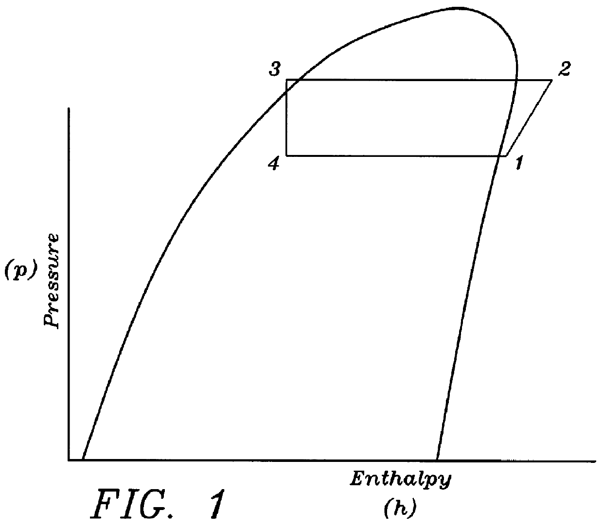
FIG. 1 is a pressure enthalpy diagram of the typical vapor compression cycle without the present invention.

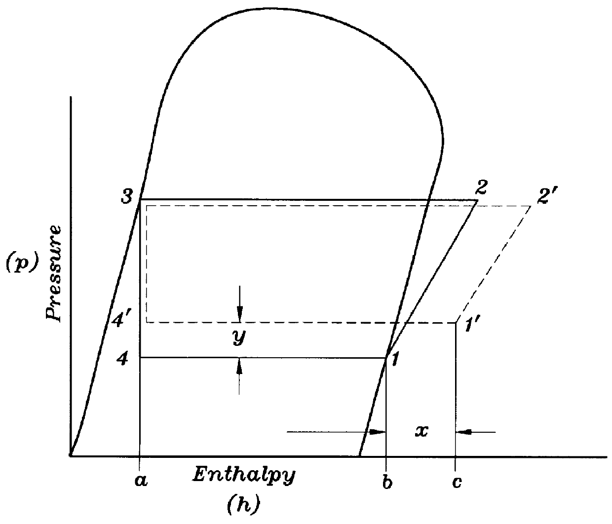
FIG. 1a is a pressure...


PUM


Abstract

A dual (or multi) sectional evaporator system comprising first and second (or more) evaporator sections capable of cooling the air supply through the evaporator. The first evaporator section is positioned upstream of the second evaporator section (second upstream of the third and so on). However, the warmest refrigerant passes through the first evaporator section and the coldest refrigerant passes through the second evaporator section (or last evaporator section if more than two sections), such that the air supply is precooled prior to reaching the second (or last) evaporator. Providing a two (or more) passes of refrigerant through the dual (or multi) sectional evaporator system increases the superheat temperature out of the first evaporator up to about 25 degrees Fahrenheit, and / or increases the mass flow of refrigerant because of the increased heat exchange efficiency provided by counterflow heat exchange. Moreover, in the preferred embodiment for an A-coil or slant coil, the second evaporator section is positioned over the top of the first evaporator section such that the second evaporator overlays the first evaporator section in order to maximize the use of available space. Also, A-coil or slant coil forms of the present invention are configured such that they include contoured cut-out shaped corner portions wherein the squared corners of the evaporators are substantially eliminated thereby eliminating the dead air flow spaces typically associated with other known evaporators. The elimination of the dead air space allows the system to operate at a lower fan speed as well as allows the system to be constructed and operate within smaller confines.

Description

1. Field of the InventionThe present invention relates to a dual (or multi) sectional evaporator system of increased refrigeration capacity for use with any air conditioner, refrigeration or heat pump system. This invention more particularly pertains to an apparatus and method comprising a dual (or multi) sectional evaporator system allowing air to first pass through the warmest sections of an evaporator and then to pass through the coldest sections of the evaporator which provides for 2 (or more) exposures of the air stream to the same refrigerant.2. Description of the Background ArtPresently there exist many types of devices designed to operate in the thermal transfer cycle. The vapor-compression refrigeration cycle is the pattern cycle for the great majority of commercially available refrigeration systems. This thermal transfer cycle is customarily accomplished by a compressor, condenser, throttling device and evaporator connected in serial fluid communication with one another. T...

Claims


Application Information

Patent Timeline
Patent Type & Authority Patents(United States)
IPC IPC(8): F24F1/00F25B39/02F24F1/0063F24F1/0067
CPCF24F1/0059F25B39/02F24F1/0067F24F1/0063
Inventor HEBERT, THOMAS H.
Owner OLIVE TREE PATENTS 1
Why Eureka
Try Eureka