Twin chopper device for spray-up molding

Inactive Publication Date: 2000-10-03
CAMOPLASY INC
View PDF12 Cites 8 Cited by
  • Summary
  • Abstract
  • Description
  • Claims
  • Application Information

AI Technical Summary

Benefits of technology

By adding a second rotatable cutter assembly, which is a mirror image of the first cutter assembly on the other side of the resin spray and by directing an even quantity of cut fibers on both sides of the resin spray and at substantially the same discharging speed, the contact surface is doubled and an adequate centering and uniform distribution of the glass fibers in the resin is achieved.
With resins and rapid wetting filaments, an instantaneous improved compaction can be obtained which enables to reduce considerably manpower used for the formation of the mixture of cut fibers and resin and for the repair of entrapped air bubbles. Lamination is also reduced thereby enabling a better control of the thickness of the sprayed material as compared to the conventional methods of spray-up molding.
The benefits of a device made in accordance with the present invention combine the effects of load reduction at the extremity of the robot arm, the torque constancy independently of the position of the robot and, consequently, of the filament discharge, as well as an acceleration / deceleration cycle of about less than a second (conventional systems require more than 6 seconds with pneumatic motors). Furthermore, the cutting speed no longer affects the performances since it is now possible to have a motor with a much higher torque. Such driving enables to achieve projections with very high or very low fiber glass discharge.
Furthermore, the chopper device of the present invention enables to apply a constant pressure on the blades of the rubber cutter rollers. A small pneumatic cylinder, which is pressure regulated, displaces the axis of the rubber roller to and from the blade roller. Notwithstanding the wear of the blades, the cutting pressure is maintained constant, which increases the useful life of the components. The withdrawal action of the roller enables rapid and more efficient maintenance interventions.

Problems solved by technology

Hence, depending on the traveling direction of the cutter and the resin gun, a rich mixture of resin is obtained on one side but a poor mixture is present on the other side; hence, when lamination is then carried out on the mixture, this difference creates conformation variations and high risk of air bubbles or voids while contributing to varying thicknesses.
Furthermore, the presence of areas which are resin rich near the coating favours the creation of cracks under stress conditions occurring during the use and operation of the molded product.

Method used


Image

  • Twin chopper device for spray-up molding
  • Twin chopper device for spray-up molding
  • Twin chopper device for spray-up molding

Examples


Embodiment Construction

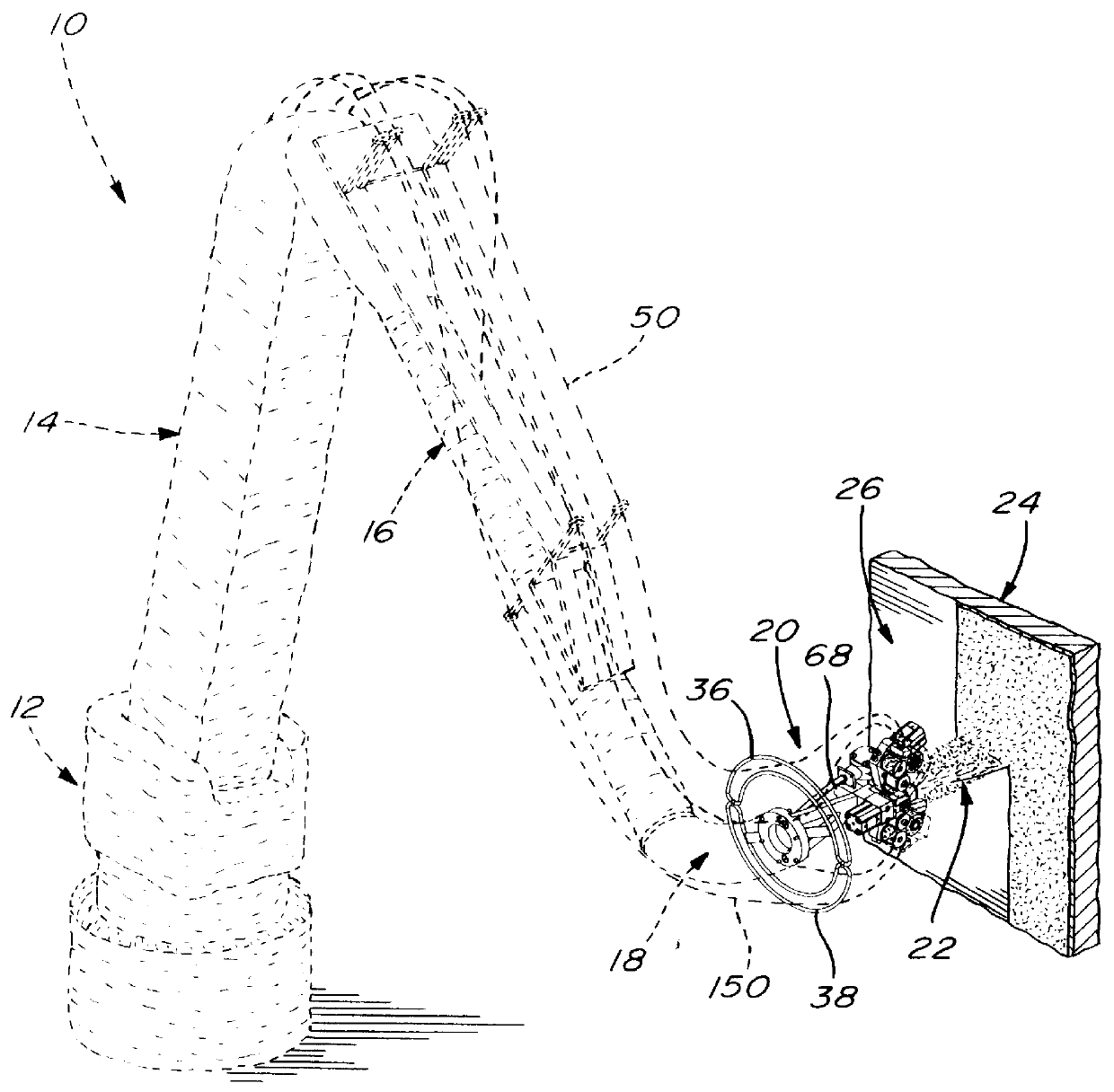
Referring to FIG. 1, there is shown in dotted lines a robot 10 consisting of a series of articulatable sections 12, 14, 16 and 18; the construction of such robot is well known in the field of spray-up molding and needs not be described in detail. A twin chopper device made in accordance with the present invention, generally identified at 20, is mounted to the robot arm section 18 for spraying a stream 22 consisting of a mixture of resin and chopped glass fibers onto a mold surface 24 which is usually coated with a gel coat 26.

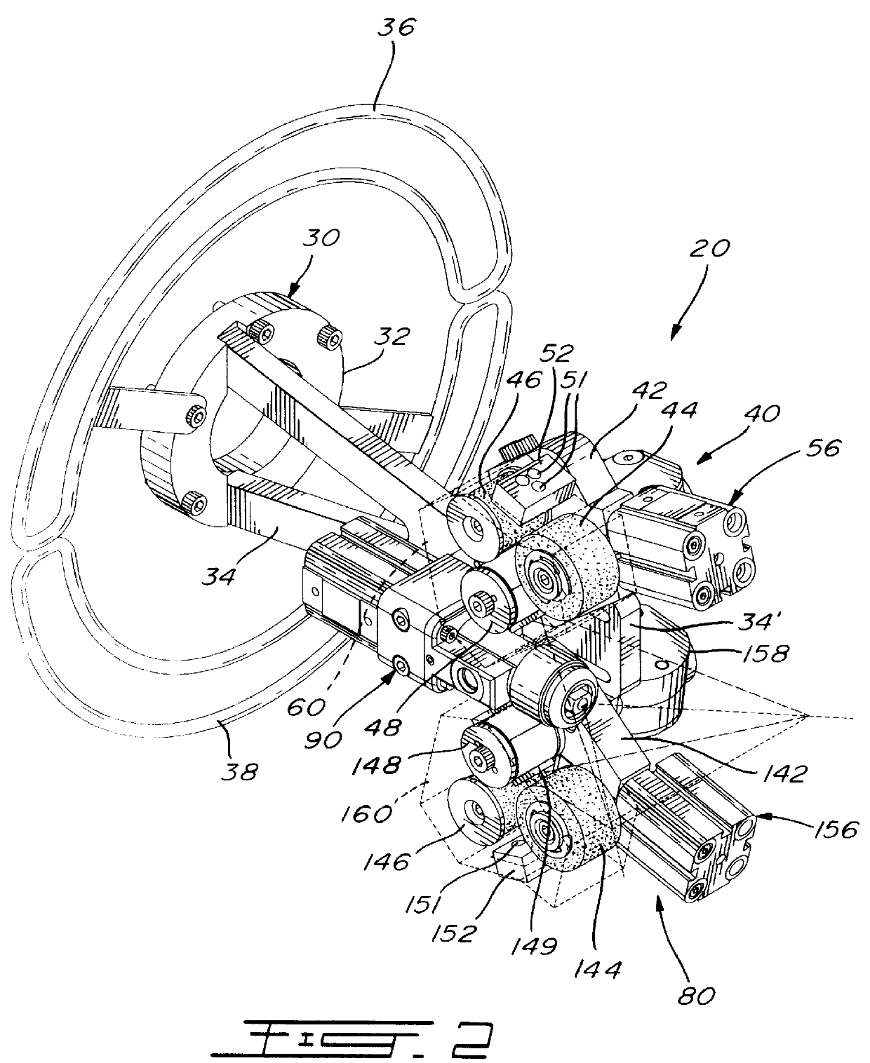
Referring to FIG. 2, the twin chopper device includes a support assembly 30 for connecting the chopper device to the robot arm. The support assembly comprises a central annular bracket 32 adapted to be connected to the robot arm section and to which is mounted a V-shaped supporting frame 34 and two semi annular loops 36 and 38 used to allow passage of fiberglass filaments therethrough, as further described hereinbelow.

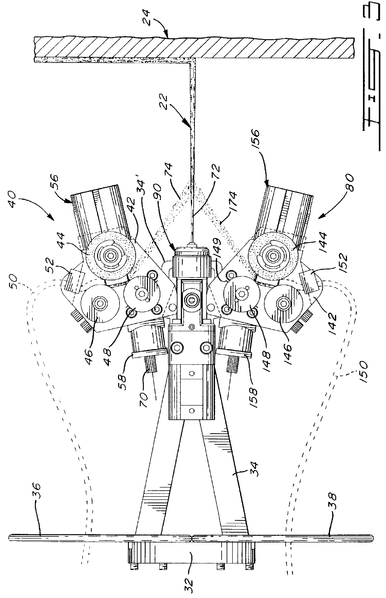
Referring also to FIGS. 3, 4 and 5, the twi...


PUM

PropertyMeasurementUnit
Angleaaaaaaaaaa
Flexibilityaaaaaaaaaa

Abstract

The twin chopper of the present invention consists of a pair of roving choppers, each chopper being disposed on either side of a resin spraying nozzle. Each chopper comprises a rotatably driven cutter roller, a rotatable friction roller cooperating with the cutter roller, and an idler roller cooperating with the friction roller for feeding roving strands between the friction roller and the cutter roller. The outlet of the first chopper is so disposed relative to the nozzle as to discharge cut rovings over and onto the flat spray of resin while the outlet of the second chopper is so disposed relative to the nozzle as to discharge cut rovings under and onto the flat spray so that the resin spray is coated with roving cuts on both sides thereof from both choppers as the spray is directed onto the open mold surface.

Description

The present invention relates to an improved roving chopping device used in combination with a resin spray gun for spraying a mixture of resin and glass fiber onto an open mold surface.In the industry of composite material, for structural and cosmetic products having dimensions of some importance, the projection of fiber glass followed up by lamination is a process which has been used for quite sometime. It has always occupied an important part of small lot market due to the low cost of molds which is balanced off by the high cost of manpower. In the 90's, the robotization of this process has enable to accelerate the production cycle, to reduce thickness variations and, consequently, to considerably increase the profitability of higher volume lots.In general, the process consist in projecting a coating of unsaturated polyester or in thermoforming an acrylic sheet on an open mold. Thereafter, chopped glass fibers are added simultaneously with a catalyzed liquid resin by either manual...

Claims


Application Information

Patent Timeline
IPC IPC(8): B05B7/14B29C41/34B29C41/36B29C70/04B29C70/38B29C70/30
CPCB05B7/1495B29C41/365B29C70/305B05B7/1409Y10S239/08B05B13/0431
Inventor COTE, MARCFERLAND, JEAN-FRAN.CEDILLA.OISGAGNE, SYLVAIN
Owner CAMOPLASY INC
Why Eureka
Try Eureka