Coupled real time emulation method for positioning and location system

a real-time emulation and positioning system technology, applied in wave based measurement systems, instruments, transmission systems, etc., can solve problems such as inability to test the accuracy and errors of a global positioning/inertial integrated system installed on-board vehicles while stationary, and inability to solve difficult problems, so as to reduce the number of real flight tests, reduce the number of simulation methods, and reduce the effect of cos

Inactive Publication Date: 2000-10-03
AMERICAN GNC
View PDF1 Cites 84 Cited by
  • Summary
  • Abstract
  • Description
  • Claims
  • Application Information

AI Technical Summary

Benefits of technology

It is a further object of this invention to provide a coupled real time emulation method for positioning and location system which allows unlimited dynamic test and performance evaluation of a global positioning/inertial integrated system because the motion devices are removed from the navigation system. With the gyro, accelerometer, and global positioning system receiver emulation method and system the testers are able to test the global positioning/inertial integrated system performance over a real mission trajectory.
It is still a further object of this invention to provide a coupled inertial sensor and global positioning system emulation method and system that is efficiently utilized for ground test of installed system, laboratory hardware-in-the-loop dynamic simulation, and global positioning/inertial integrated system analysis and development.
Another object of this invention is to provide a coupled real time e

Problems solved by technology

There are commonly unsolved difficult problems in the ground tests and laboratory hardware-in-the-loop tests of the coupled inertial/global positioning system on-board a vehicle such as aircraft, ship and car.
In the ground test, since the vehicle is stationary, the inertial sensor in the global positioning/inertial navigation system can not produce dynamic electronic signals for it is a self-contained device, and the global positioning system receiver can not output dynamic measurements.
In other words, it is unable to test the accuracy and errors of a global positioning/inertial integrated system installed on-board vehicle while it is stationary.
However, if the vehicle to be test

Method used


Image

  • Coupled real time emulation method for positioning and location system
  • Coupled real time emulation method for positioning and location system
  • Coupled real time emulation method for positioning and location system

Examples


Embodiment Construction

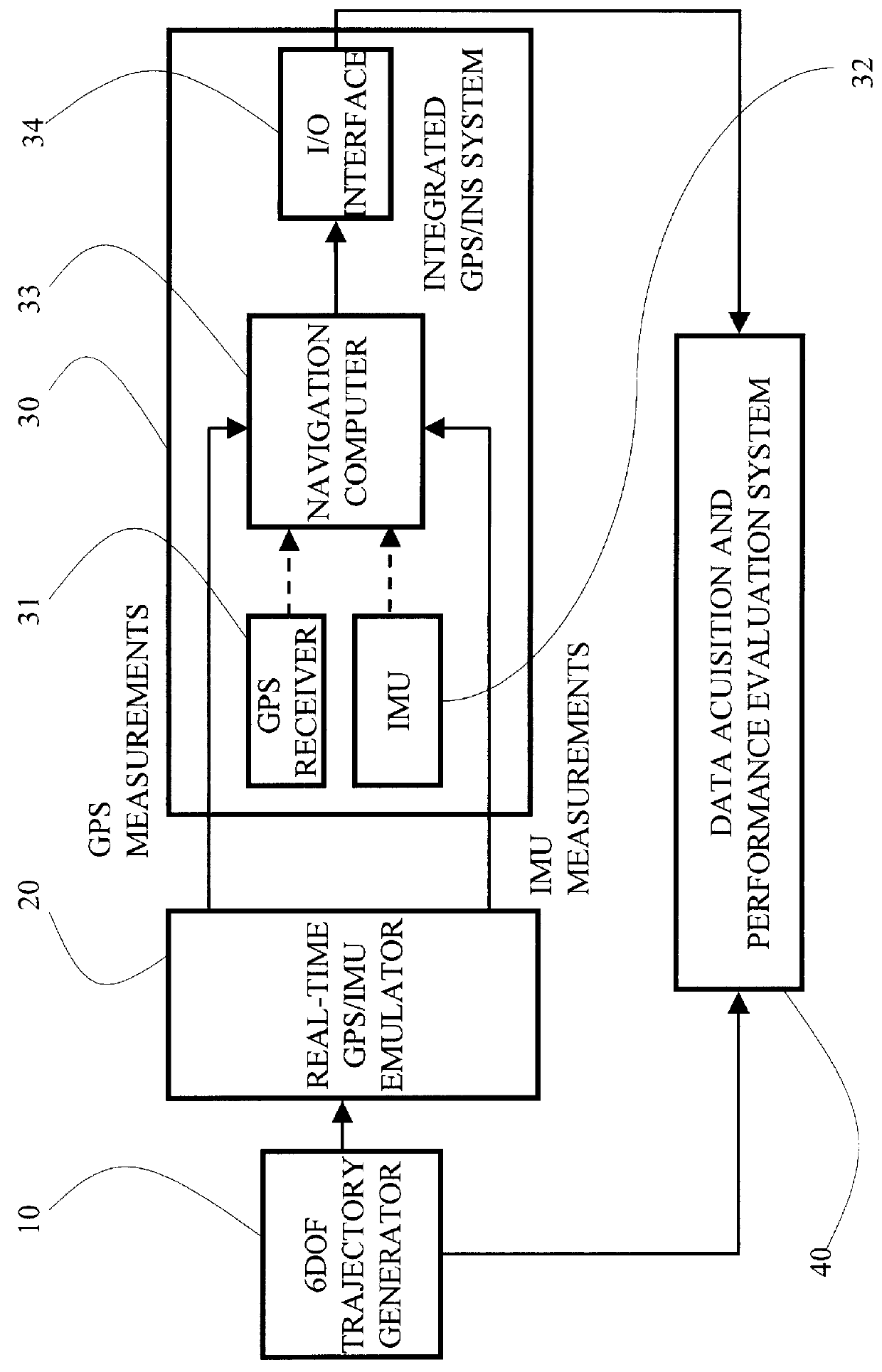
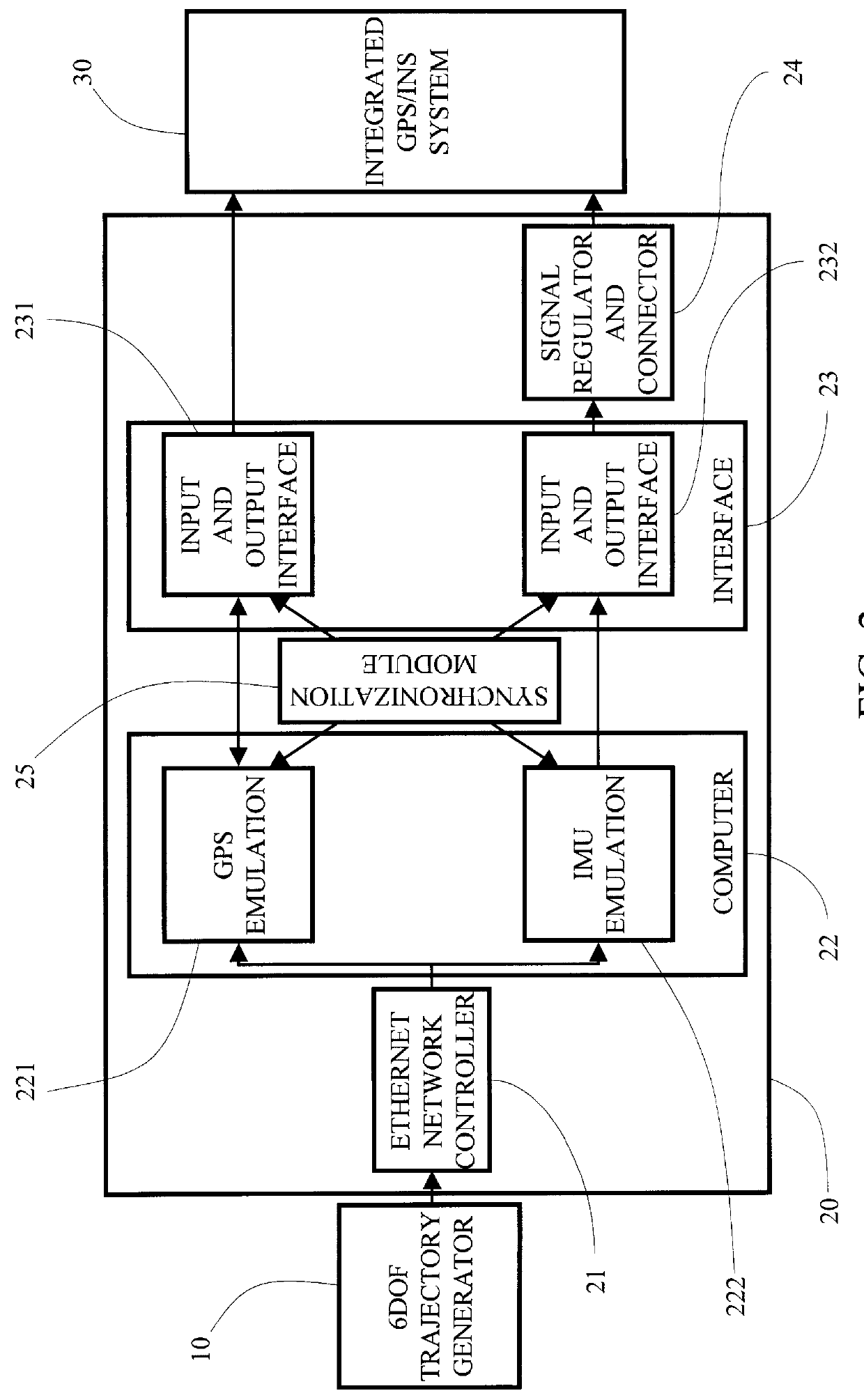
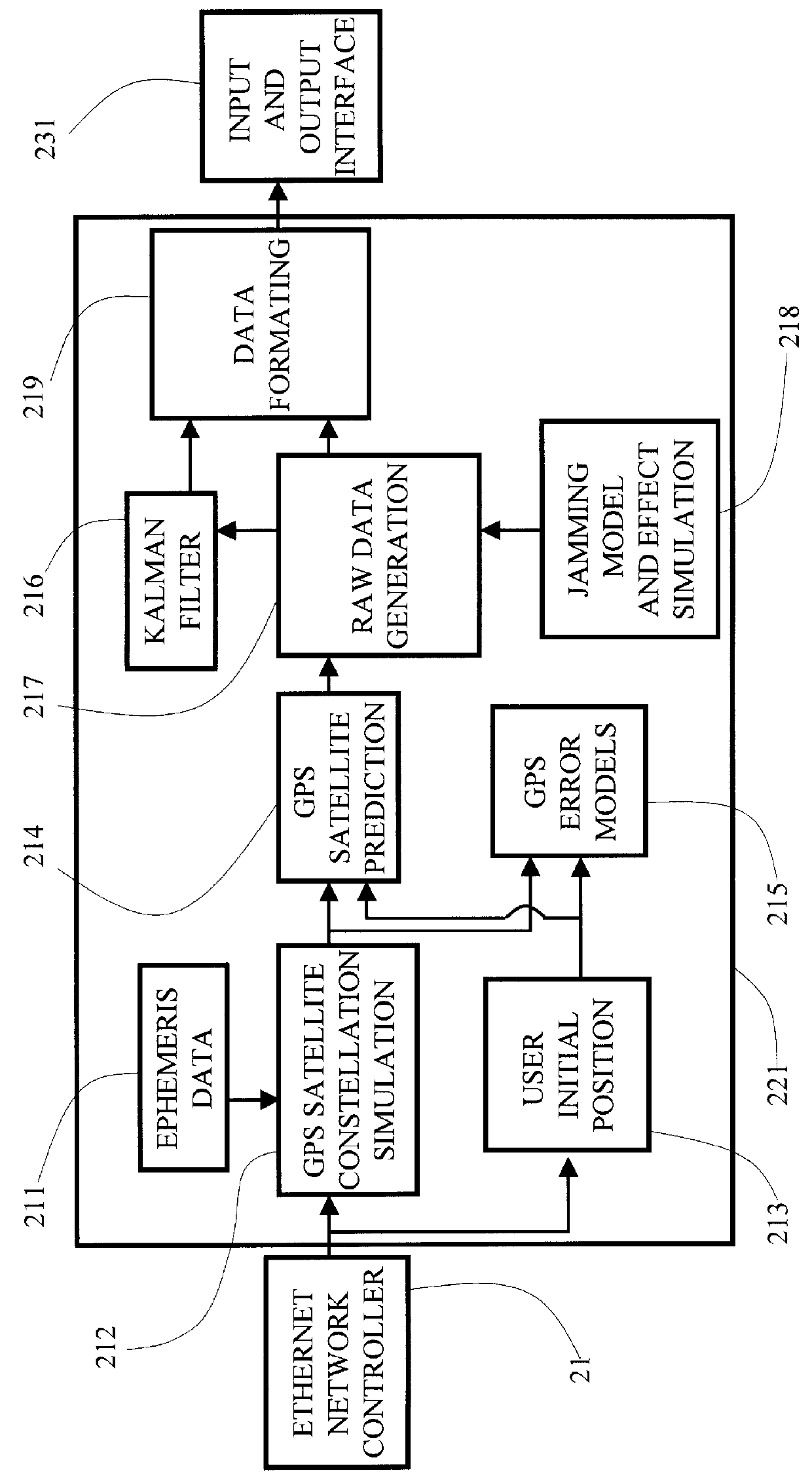
The present invention relates to a method and system for coupled (global positioning system / inertia measurement unit) GPS / IMU sensor emulation. The technique involves IMU modeling, IMU error modeling, GPS receiver modeling, GPS error modeling, and simulated data formatting. During the hardware-in-the-loop test, a 6DOF trajectory generator drives the present system to produce dynamic IMU and GPS measurements. These simulated data and signals are injected into the integrated GPS / INS system. The advantages of the technique applied in the present invention include:

1. Simulating dynamic IMU measurements in real time using software;

2. Simulating the behavior of a GPS receiver in a dynamic and jamming environment using software;

3. Simulating the GPS and IMU simultaneously using synchronization technique;

4. Having unlimited dynamic IMU sensors and GPS receiver simulation capability coupled with a 6DOF generator; and

5. Providing a cost-effective test method for the GPS / INS system and its cos...


PUM


Abstract

A coupled real time emulation method for positioning and location system includes the steps of receiving real time trajectory data from a 6DOF trajectory generator and generating global positioning system simulated measurements and inertial measurement unit simulated electronic signals which are injected into an on-board integrated global positioning system/inertial measurement unit system. When the on-board integrated global positioning system/inertial measurement unit system is excited in dynamic operation, a performance thereof is able to be tested and evaluated as if carrying a real transportation test.

Description

FIELD OF THE PRESENT INVENTIONThe present invention relates to a global positioning system and receiver emulation, a gyro and accelerometer emulation, and more particularly to a coupled real time emulation method of global positioning system, gyro and accelerometer for a hardware-in-the-loop integrated positioning system test on the ground.BACKGROUND OF THE PRESENT INVENTIONThere are commonly unsolved difficult problems in the ground tests and laboratory hardware-in-the-loop tests of the coupled inertial / global positioning system on-board a vehicle such as aircraft, ship and car.In the ground test, since the vehicle is stationary, the inertial sensor in the global positioning / inertial navigation system can not produce dynamic electronic signals for it is a self-contained device, and the global positioning system receiver can not output dynamic measurements. In other words, it is unable to test the accuracy and errors of a global positioning / inertial integrated system installed on-bo...

Claims


Application Information

Patent Timeline
IPC IPC(8): G01S1/00G01S19/48
CPCG01S19/23G01S19/49
Inventor LIN, CHING-FANG
Owner AMERICAN GNC
Why Eureka
Try Eureka