Dielectric catalyst structures

a technology of dielectric catalysts and catalyst materials, applied in the field of dielectric catalyst materials, can solve the problems of large and expensive prior art reactors, and achieve the effect of reducing the operating cost and increasing the efficiency of such reactors

Inactive Publication Date: 2000-10-10
GLOBALFOUNDRIES INC
View PDF48 Cites 15 Cited by
  • Summary
  • Abstract
  • Description
  • Claims
  • Application Information

AI Technical Summary

Benefits of technology

It is a purpose of the invention to provide a dielectric catalyst structure which can be utilized in a catalytic reactor, especially a reactor which produces high electric fields or corona discharge, to increase the efficiency and lower the operating costs of such reactor.
It is another purpose of the present invention to provide a catalyst structure which decreases the voltage required to produce an electric field of a given strength.
It is yet another purpose of the present invention to provide a catalyst structure which permits a catalytic reactor in which the structure is used to be reduced in size.

Problems solved by technology

Typically, prior art reactors are large and expensive.

Method used


Image

  • Dielectric catalyst structures
  • Dielectric catalyst structures
  • Dielectric catalyst structures

Examples


Embodiment Construction

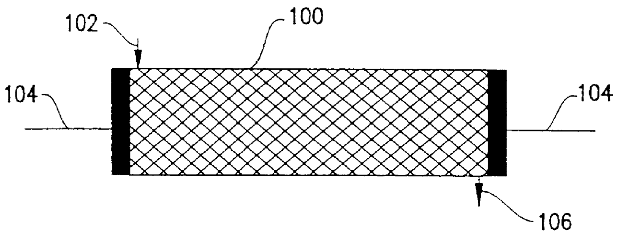
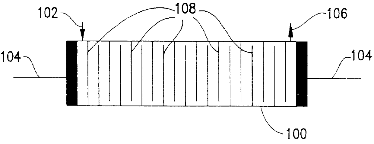
A preferred embodiment of the present invention is a catalytic reactor, preferably a multi-surface reactor for corona destruction of volatile organic compounds (VOCs). In a first preferred embodiment, as represented schematically in FIG. 1, the reactor includes a vessel 100 filled with catalyst coated substrate pieces (as represented by the cross-hatching). Preferably, vessel 100 is cylindrical. Noxious or polluting gas enters reactor vessel 100 through an inlet 102. Alternating current (AC) is applied to reactor 100 at electrodes 104 to generate a corona therein. Preferably, electrodes 104 are located at opposite ends of the cylindrical reactor vessel 100. A gaseous mixture of unwanted gases such as volatile organic compounds, e.g. hydrocarbons, chlorinated hydrocarbons and desirable gases, e.g. air, enters reactor vessel 100 filters through the catalyst coated substrate pieces, exiting through outlet 106. Gas in the reactor is exposed to the corona in the presence of the catalyst ...


PUM

PropertyMeasurementUnit
thicknessaaaaaaaaaa
thicknessaaaaaaaaaa
thicknessaaaaaaaaaa

Abstract

A reactor for corona destruction of volatile organic compounds (VOCs), a multi-surface catalyst for the reactor and a method of making the catalyst for the reactor. The reactor has a catalyst of a high dielectric material with an enhanced surface area. A catalyst layer stack is formed by depositing a high dielectric layer on a substrate and, then depositing a conductive layer on the dielectric layer. The catalyst layer stack is bombarded by low RF energy ions to form an enhanced surface area and to form a protective layer over the conductive layer. Catalyst layer stacks may be joined back to form double-sided catalyst layer stacks. The catalyst layer stack may be diced into small pieces that are used in the reactor or the whole catalyst layer stack may be used.

Description

1. Field of the InventionThe present invention relates to catalyst materials, and more specifically to dielectric catalyst materials for use in catalytic reactors which produce high electric fields or corona discharge.2. Background DescriptionCorona destruction of volatile organic compounds (VOCs) is a method of disposing of noxious or toxic gases or other atmospheric contaminants or pollutants. The unwanted gas is decomposed into a less polluting gas that may be vented into the atmosphere. The unwanted gases, generally VOC, are passed over a bed of catalyst in a reactor, while a high alternating current (AC) voltage is passed across the bed to produce a corona discharge. A dielectric material catalyst in the reactor produces a stable corona and the VOCs are converted to CO.sub.2 gas.Typically, prior art reactors are large and expensive. Further these large reactors require, typically, at least 10 kilovolts (kV) to generate the corona.Thus, there is a need for cheaper, smaller, more...

Claims


Application Information

Patent Timeline
Patent Type & Authority Patents(United States)
IPC IPC(8): B01D53/86B01D53/32B01J35/00B01J37/02B01J37/00F01N3/08F01N3/20F01N3/10
CPCB01D53/32B01D53/864B01D53/8662B01D53/8668B01D53/8678B01J35/0033B01J37/0244F01N3/0892F01N3/10F01N3/2013B01D2257/2064Y02T10/26B01D2257/702Y02T10/12
Inventor NAEEM, MUNIR-UD-DIN
Owner GLOBALFOUNDRIES INC
Why Eureka
Try Eureka