Fuel injection valve for high pressure injection

a fuel injection valve and high pressure technology, applied in the direction of electric control, combustion air/fuel air treatment, machines/engines, etc., can solve the problems of long line connections that are acted on by high voltage and generate noise fields to be routed to the individual fuel injection valves, and the heat that remains in the electrical control circuit has to be dissipated in a sufficient manner, so as to reduce the power loss due to voltage drop and reduce the effect of noise radiation

Inactive Publication Date: 2000-10-17
ROBERT BOSCH GMBH
View PDF6 Cites 14 Cited by
  • Summary
  • Abstract
  • Description
  • Claims
  • Application Information

AI Technical Summary

Benefits of technology

The fuel injection valve according to the invention has the advantage over the prior art that the electrical control circuit is subdivided into a first circuit part and second circuit parts which are each provided directly on the fuel injection valve and which include control of the power supply to the electromagnet. It is particularly advantageous to provide the elements of the circuit in the second circuit part, which contain the power components and capacitors of the electrical control circuit. The heat produced particularly in the power components, capacitors, end stages, and diodes is distributed to the individual injection valves and can be dissipated there in an optimal fashion without further expenditure for a control of cooling devices. In particular, this prevents long lines that are highly affected by current from having to be provided. The power losses due to voltage drop are reduced and also, high-stress plug connections are avoided since the high currents only occur in the second circuit part and are guided immediately to the magnet in the shortest line connection. The short lines, moreover, have the additional advantage that noise radiation is reduced, which in particular can have an effect on the electrical circuit of the control device. The first part of the control circuit is reduced to the signal processing part of the circuit, which no longer experiences interference from feedback by means of the power part, which is respectively required for triggering the solenoid valve.

Problems solved by technology

This disposition, though, has the disadvantage that long line connections that are acted on by high voltages and generate noise fields must be routed to the individual fuel injection valves.
Furthermore, due to the available capacity for rapidly opening and closing of the solenoid valves, the heat that remains in the electrical control circuit has to be dissipated in a sufficient manner.
This is connected with an additional expense.

Method used


Image

  • Fuel injection valve for high pressure injection

Examples


Embodiment Construction

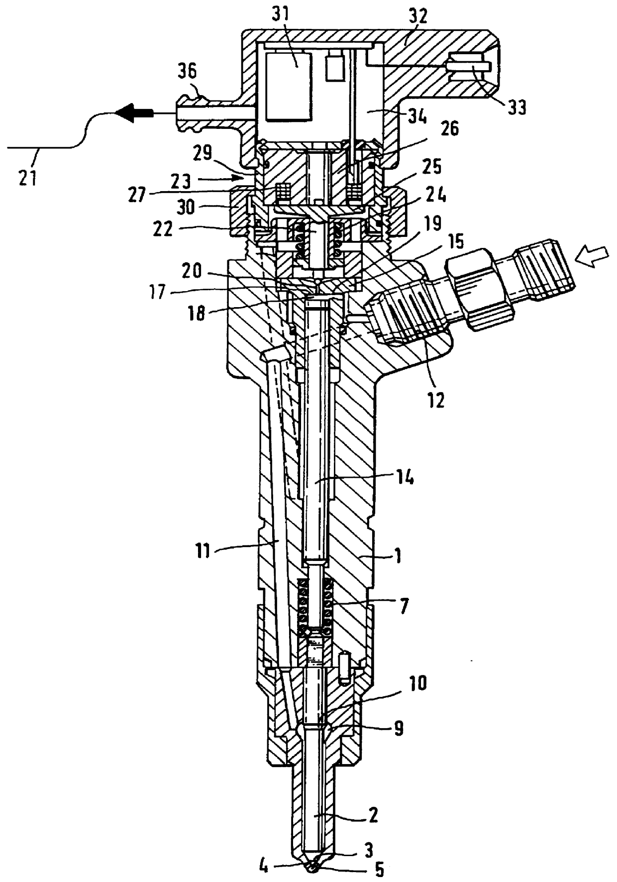
The housing 1 of the fuel injection valve contains a valve closing member 2 with a conical sealing face 3, which comes into contact with a conical valve seat 4, from which injection bores 5 lead. The valve member is then acted upon by means of a compression spring 7 in the closing direction toward the valve seat 4. In the intermediary region of the valve closing member 2, a pressure chamber 9 is provided inside the housing with a pressure surface 10 that points in the opening direction of the valve closing member subjected to the pressure prevailing there. The pressure is supplied to the pressure chamber 9 via a high pressure supply line 11. The high pressure supply line communicates with a high pressure reservoir, not shown in detail, via a high pressure connection 12 that leads away perpendicular to the longitudinal axis of the injection valve. Coaxial to the compression spring 7, moreover, the valve closing member 2 is engaged by a tappet 14 which, with its end face 17, defines a...


PUM


Abstract

PCT No. PCT/DE96/02378 Sec. 371 Date Jan. 14, 1998 Sec. 102(e) Date Jan. 14, 1998 PCT Filed Dec. 11, 1996 PCT Pub. No. WO97/43542 PCT Pub. Date Nov. 20, 1997A fuel injection valve which is provided for high pressure injection in self-igniting internal combustion engines and has a solenoid valve for controlling the injection. To trigger this solenoid valve, a control circuit is provided which is subdivided into a first circuit part and a second circuit part. The second circuit part is separate from the first circuit part, which jointly serves to control a number of injection valves, and are disposed on each individual injection valve. The housing is clipped onto the fuel injection valve and fuel flows through its interior for cooling purposes.

Description

PRIOR ARTThe invention is based on a fuel injection valve for high pressure injections. U.S. Pat. No. 4,972,997 has disclosed a fuel injection valve of this kind, which is supplied with fuel from a high pressure reservoir. The control of the injection is carried out in an electrohydraulic manner by virtue of the fact that the high pressure fuel source supplies pressurized fuel to a control chamber. This control pressure is used to keep the valve member of the fuel injection valve in the closed position since the control surface acted on by the control pressure is greater than the surface impinged upon on the fuel injection valve. The control chamber continuously communicates with the high pressure fuel source via a first throttle and can be relieved via a second throttle that is controlled by a solenoid valve. As soon as the solenoid valve opens the second throttle, the control chamber is discharged and the pressure on the pressure surfaces of the valve member of the injection valve...

Claims


Application Information

Patent Timeline
Patent Type & Authority Patents(United States)
IPC IPC(8): F02M59/00F02D41/00F02M59/46F02M47/02F02M51/00F02M51/06
CPCF02D41/00F02M47/027F02M51/005F02M63/0036F02M63/0017F02M2700/077F02M2547/003F02M51/00F02M47/02
Inventor BRONKAL, BERNHARD
Owner ROBERT BOSCH GMBH
Why Eureka
Try Eureka