Radiation image detecting system

a technology of radiation image and detection system, which is applied in the field of radiation image detection system, can solve the problems of power supply failure, power supply failure, radiography, etc., and achieve the effect of reducing power loss owing to cable voltage drop, reducing current carrying capacity of cable, and improving the pulling-around property of radiation image detecting apparatus

Active Publication Date: 2012-01-12
KONICA MINOLTA MEDICAL & GRAPHICS INC
View PDF1 Cites 6 Cited by
  • Summary
  • Abstract
  • Description
  • Claims
  • Application Information

AI Technical Summary

Benefits of technology

[0023]According to this invention, the current-carrying capacity of the cable can be made to be small by reducing the charging current when the radiation image detecting apparatus is connected to the cable, and consequently the cable can be thinned to improve the pulling-around property of the radiation image detecting apparatus.
[0024]Moreover, because the current flowing through the cable and the charge controlling circuit can be made to be small, the power loss for the voltage drop owing to the cable can be reduced, and the heat generation in the charge controlling circuit becomes small and the quantity of noise generated from the charge controlling circuit can be suppressed. Thereby, the deterioration of image quality owing to the heat and the noise can be suppressed.
[0025]Furthermore, the radiation image detecting apparatus can be charged with a large current when the radiation image detecting apparatus is connected to the cradle, and has an effect of enabling charging in a short time.

Problems solved by technology

However, when the radiation image detecting apparatus is driven by an internal battery, it may happen that the battery runs out in process of radiography, transfer processing of image data, or the like.
In this case, a disadvantage that the radiography, the transfer processing of image data, or the like must be recommenced is brought about.
However, when it is tried to make a charging current large in order to shorten the charging time, the diameter of the cable for power supply cannot help being thick in order to secure the current-carrying capacity thereof, and a problem of the inconvenience to pull the radiation image detecting apparatus around arises.

Method used


Image

  • Radiation image detecting system
  • Radiation image detecting system
  • Radiation image detecting system

Examples


first embodiment

[0038]A first embodiment of the radiation image detecting system according to the present invention will first be described with reference to FIGS. 1-7. However, the embodiments to which the present invention can be applied are not limited to the ones shown in the drawings.

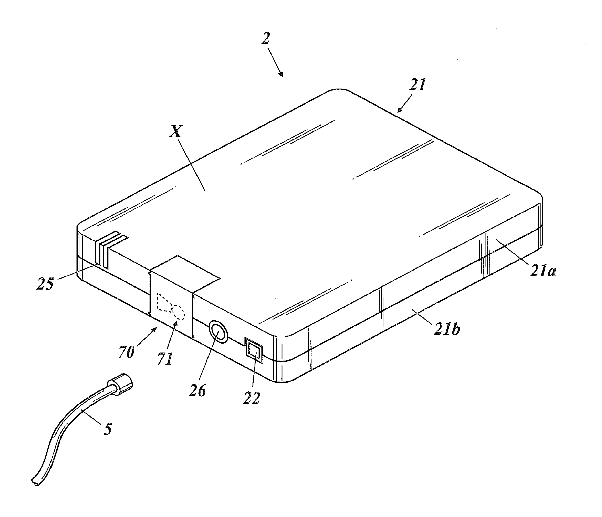
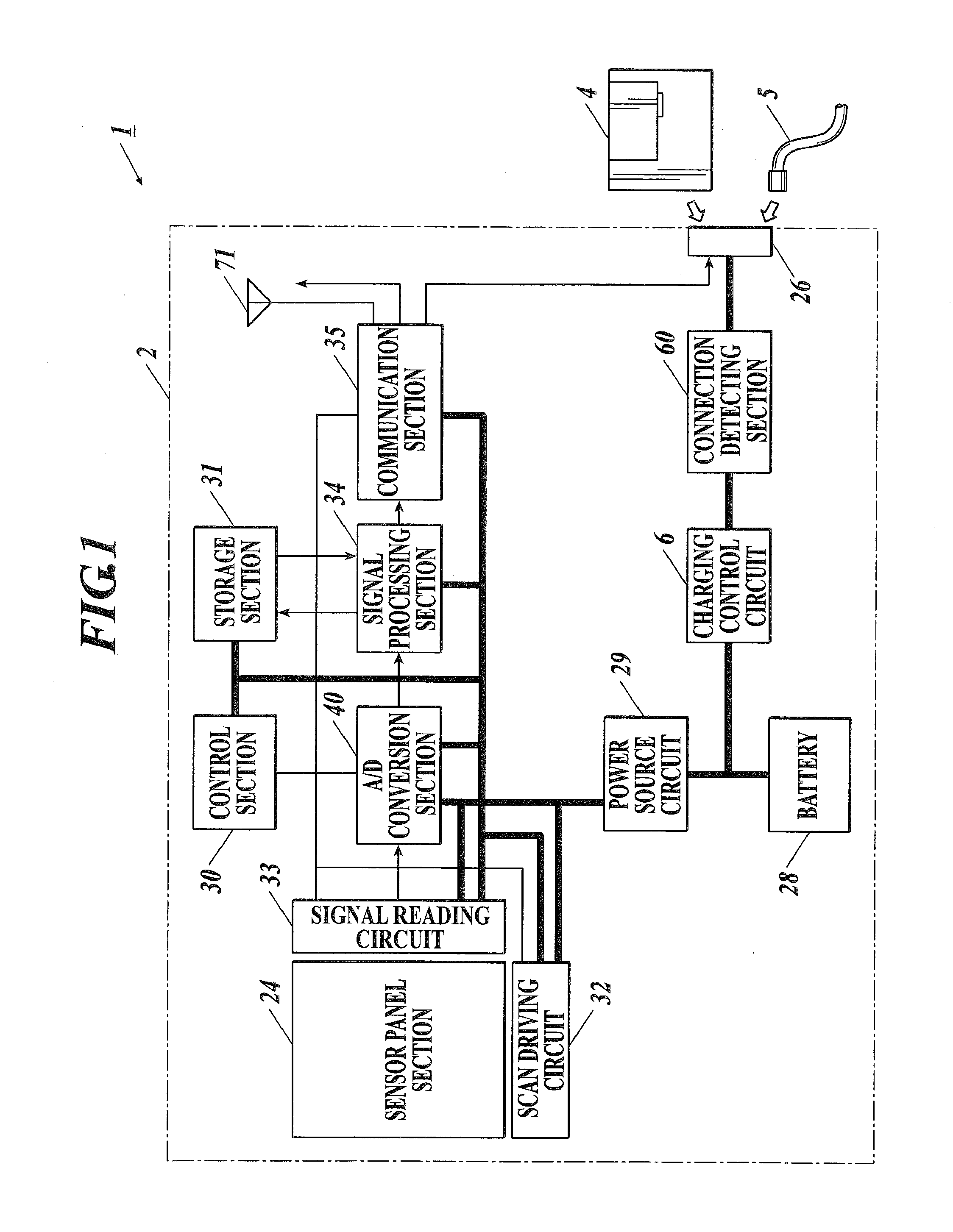
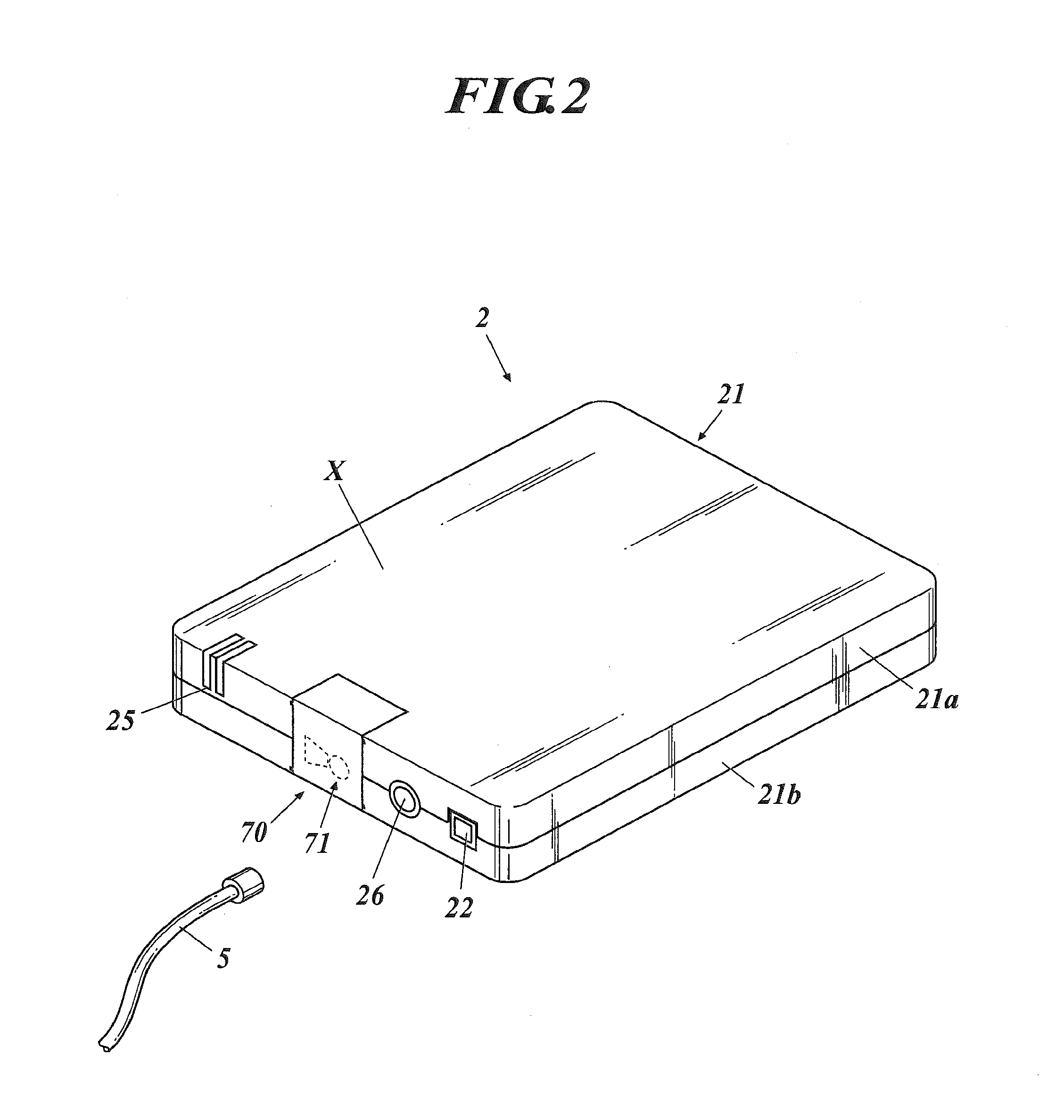
[0039]A radiation image detecting system 1 according to the present embodiment, as shown in FIG. 1, includes a radiation image detecting apparatus 2, a cradle 4 on which the radiation image detecting apparatus 2 is placed, and a cable 5 connected to the radiation image detecting apparatus 2.

[0040]The cradle 4 supplies electric power to the radiation image detecting apparatus 2 from the outside by placing the radiation image detecting apparatus 2 thereon. As shown in FIG. 4, the cradle 4 includes an AC / DC constant voltage power source 41, to which a plug receptacle 8 to be connected to a not-shown external power source is connected, and output connector sections to output the electric power supplied from the AC / DC ...

second embodiment

[0134]Next, a second embodiment of the present invention will be described with reference to FIGS. 9-11. Incidentally, the second embodiment is different from the first embodiment in the configuration of a charge controlling circuit to control the charging of a battery, and the point different from that of the first embodiment will especially be described in the following.

[0135]As shown in FIG. 9, a radiation image detecting system 200 is equipped with the radiation image detecting apparatus 2, the cradle 4, and the cable 5 in the present embodiment similarly to the first embodiment.

[0136]The cradle 4 is provided with a charge controlling circuit 9 equipped with a charging current setting section 91, a switch control section 92, a charging switch 93, an inductor 94, a charging current detecting section 95, and a battery voltage detecting section 96. The charge controlling circuit 9 performs the setting of the current value of a charging current to be supplied to the battery 28 and t...


PUM


Abstract

Provided is a radiation image detecting system including a cassette type radiation image detecting apparatus capable of being driven by electric power supplied from a built-in battery; a charge controlling circuit to control charging of the battery; a cradle supplying electric power to the radiation image detecting apparatus; and a cable supplying electric power to the radiation image detecting apparatus, wherein the radiation image detecting apparatus includes a connection section being electrically connected to each of the cradle and the cable to receive the electric power; the battery is charged by the cradle being connected to the connection section and by the cable being connected to the connection section; and the charge controlling circuit switches a charging current between a time when the cradle is connected to the connection section and a time when the cable is connected to the connection section.

Description

CROSS REFERENCE TO RELATED APPLICATIONS[0001]This is a U.S. national stage of application No. PCT / JP2010 / 052400, filed on Feb. 18, 2010. Priority under 35 U.S.C. §119(a) and 35 U.S.C. §365(b) is claimed from Japanese Application No. JP2009-071405, filed Mar. 24, 2009, the disclosure of which is also incorporated herein by reference.TECHNICAL FIELD[0002]The present invention relates to a radiation image detecting system.BACKGROUND ART[0003]Conventionally, as a medical radiation image obtaining section, a radiation image detecting apparatus, the so-called flat panel detector (FPD), in which solid state image pickup devices are two-dimensionally arranged, has been known. It is known that such a radiation image detecting apparatus is a direct system one, an indirect system one, or the like. The direct system one directly converts radiation energy into electric charges by using a photo conductive material, such as a-Se (amorphous selenium), as a radiation detecting element, and reads out...

Claims


Application Information

Patent Timeline
Patent Type & Authority Applications(United States)
IPC IPC(8): G01T1/24
CPCA61B6/4233A61B6/4283H04N5/32H01L27/14603A61B6/56
Inventor NIEKAWA, YUKIHIROEGUCHI, YOSHIHIKO
Owner KONICA MINOLTA MEDICAL & GRAPHICS INC
Why Eureka
Try Eureka