Integrated heating and fresh air supply device for use with an air distribution system

a technology of heating and fresh air supply and air distribution system, which is applied in the direction of lighting and heating apparatus, ventilation systems, heating types, etc., can solve the problems of air in the center of the room not being heated adequately, pollutant elimination is impossible to complete, and loss of usable spa

Inactive Publication Date: 2000-10-17
MARLEY ENGINEERED PRODS
View PDF22 Cites 17 Cited by
  • Summary
  • Abstract
  • Description
  • Claims
  • Application Information

AI Technical Summary

Problems solved by technology

By their nature, these pollutants are impossible to eliminate completely.
The disadvantage of these large conduits is mostly the loss of usable space due to the size of the conduits.
However, the disadvantage with these types of heating systems, i.e. both electrical and hot water, is that they do not include any ventilation and/or mixing air and the heat diffusion is only driven by free convection.
Furthermore, since air is expelled at low speed, it has a tendency to hug the wall against which the diffuser is placed, so that air in the center of a room will not be heated adequately.
This also results in loss of energy, since a portion of the heat heats the wall, which is usually in contact with the exterior.
The problem with such a diffuser is that it does not introduce fresh air into the space being heated.
Furthermore, even if warm air does not hug the wall, it is still warmer than ambient air and so has a ten

Method used


Image

  • Integrated heating and fresh air supply device for use with an air distribution system
  • Integrated heating and fresh air supply device for use with an air distribution system
  • Integrated heating and fresh air supply device for use with an air distribution system

Examples


Embodiment Construction

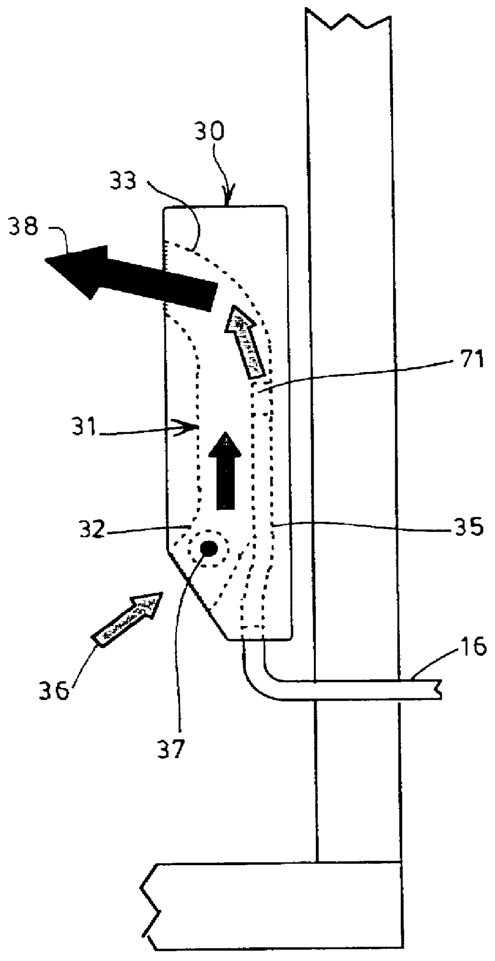
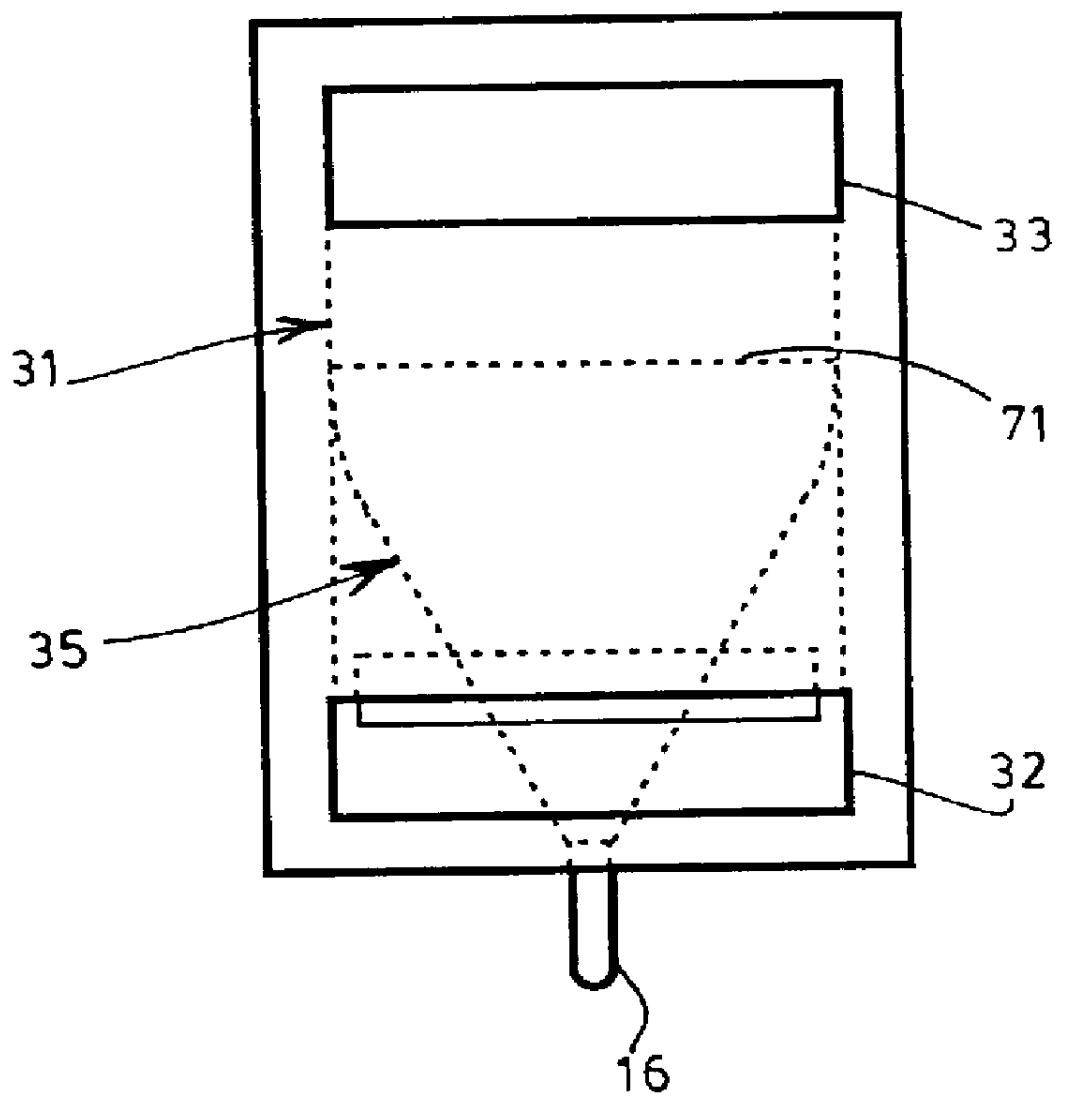
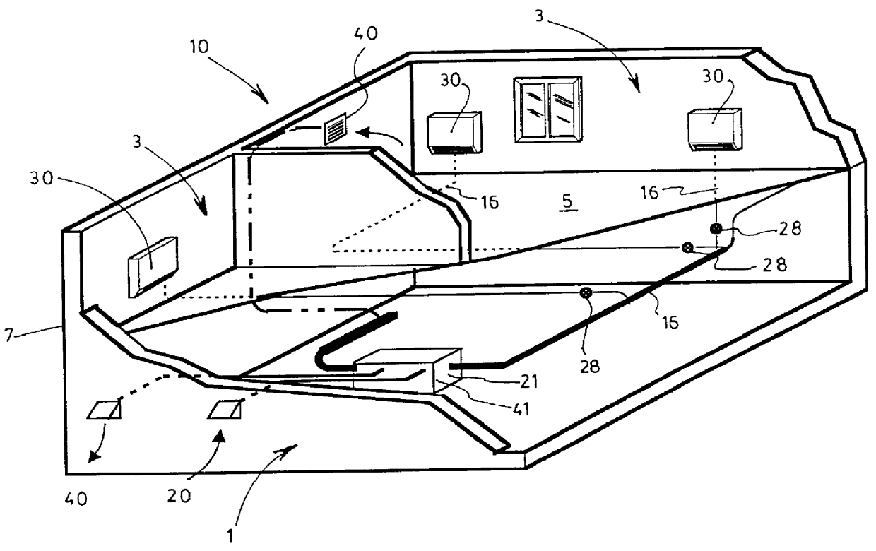
The present invention is concerned with an integrated heating and fresh air supply device for use with a decentralized air distribution system. The device will be hereinafter referred to as a "ventilation unit". A ventilation unit 30, shown in more detail in FIGS. 1 and 2 is located in a room 3 in a space such as a house or an office building, although there may be more than one per room 3, and includes a conduit 31 defining an air passage which has a first 32 and second 33 opposite ends. The ventilation unit 30 also includes a fresh air diffuser 35, operatively connected to a fresh air intake 20 through small diameter conduits 16, for outputting fresh air into the conduit 31. The diffuser 35 is preferably located near the second opposite end 33 of the conduit, as better shown on FIG. 2. The diffuser 3 5, by diffusing fresh air into the conduit 31, also draws ambient air from the room 3 into the conduit 31, as shown by arrow 36.

The ventilation unit 30 further includes heating means ...


PUM


Abstract

A ventilation unit for use with a heating or cooling system that is decentralized and does not require large conduits is disclosed. The system includes at least one fresh air intake; a fan operatively connected to the at least one fresh air intake for drawing air from outside of a space into the fresh air intake; and at least one ventilation unit located in the room. The ventilation unit includes a conduit defining an air passage having a first and second opposite ends, a diffuser operatively connected to the fresh air intake for outputting fresh air near the second opposite end of the conduit and for drawing ambient air from the room through the first opposite end. The ventilation unit also includes a heating element located downstream from the first opposite end inside the conduit. The ambient air is entrained towards the heating element which heats the ambient air, and the heated air is ventilated into the room at the second opposite end of the conduit by the action of a chimney effect and the fresh air diffuser. The system provides for adequate ventilation through the use of small conduits due to the decentralized heating of the air.

Description

The present invention relates to a ventilation unit providing fresh air and room temperature control for use as part of a decentralized heating and cooling system.DESCRIPTION OF THE PRIOR ARTDifferent methods and apparatuses have been proposed in order to ventilate a space such as a room, a house or an office building. This is an important consideration since an inhabited space will contain numerous pollutants, emanating from the space itself, from the furniture, from the external environment, and from human activity (i.e. breathing is a source of carbon dioxide (CO.sub.2), candles, etc.). By their nature, these pollutants are impossible to eliminate completely. This is why it is necessary to replace the ambient air with air in which pollutants are in smaller concentration.The most basic system is simply natural ventilation, where fresh air is introduced into a space through openings in the shell of a building. Vitiated air is exited from this space through the same openings.However...

Claims


Application Information

Patent Timeline
IPC IPC(8): F24F13/00F24F12/00F24F1/01F24F13/26
CPCF24F1/01F24F12/006F24F13/26Y02B30/563F24F2011/0002Y02B30/56
Inventor BARIBEAULT, JEANDOSTIE, MICHELPARENT, DENIS
Owner MARLEY ENGINEERED PRODS
Why Eureka
Try Eureka