

Oscillation system
a technology of oscillating system and oscillating frequency, which is applied in the direction of pulse generator, pulse technique, electrial characteristics varying frequency control, etc., can solve the problems of lowering reliability, signal value, timing, and increasing energy consumption, so as to meet the challenges of clock distribution and phase synchronization design techniques
- Summary
- Abstract
- Description
- Claims
- Application Information
AI Technical Summary
Benefits of technology
Problems solved by technology
Method used
Image

Examples
example 1
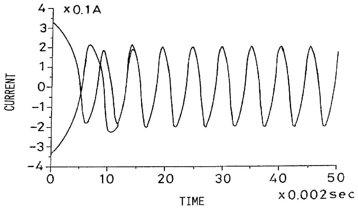
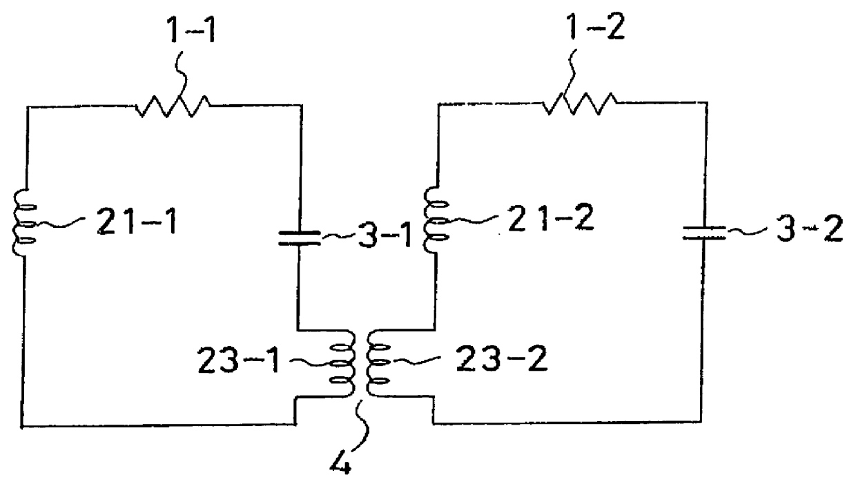
Referring to FIG. 1, a two oscillation circuits are interconnected by mutual inductance coils 23-1 and 23-2, having a negative mutual inductance to become a synchronization circuit satisfying the above equation (17).
With regard to parameter values for L.sub.0, l.sub.0 of the inductances 21, 23, the capacitance C.sub.0 of the capacitor 3, the value -m of the negative inductance 4 and r.sub.0 +r.sub.2 I.sup.2 of resistor 1, such parameters are used.
L.sub.0 +7.times.10.sup.-2 H, l=7.times.10.sup.-2 H, m=6.times.10.sup.-2 H, C.sub.0 =200 .mu.F, r.sub.0 =10 .OMEGA. and r.sub.2 =3.333.times.10.sup.2 .OMEGA. / A.sup.2,
The resulting reference oscillation frequency becomes .omega..sub.0 =500 rad / sec, with g.sub.11 =g.sub.22 =g.sub.12 =g.sub.21 =0.3 and .epsilon.=1.
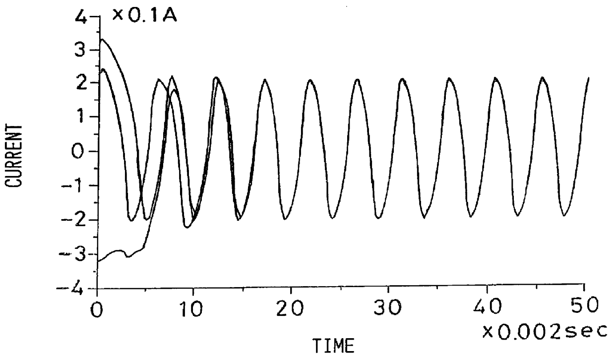
FIG. 2 illustrates waveforms of the synchronization process of the two oscillation circuits shown in FIG. 1 . From FIG. 2, it is seen that the current oscillations of the two oscillation circuits, started with arbitrary different ini...
example 2
Reffering to FIG. 3, three oscillation circuits are interconnected by mutual inductance coils having negative mutual inductance, and the resulting circuit is the synchronization circuit satisfying the equation (17).
As parameters, L.sub.0 =2.times.10.sup.-2 H, l=6.times.10.sup.-2 H, m=6.times.10.sup.31 2 H, L.sub.1 =8.times.10.sup.-2 H, C.sub.0 =200 .mu.F, r.sub.0 =10 .OMEGA. and r.sub.2 =3.333.times.10.sup.2 .OMEGA. / A.sup.2 are used as parameters, and the resulting reference oscillation frequency becomes .omega..sub.0 =500 rad / sec, with g.sub.11 =g.sub.22 =g.sub.33 =g.sub.12 =g.sub.23 =0.3, g.sub.31 =0 and .epsilon.=1, where L.sub.1 is the value of the inductances 22-1, 22-2 of both end oscillation circuit of FIG. 3.
It is assumed that circuits arranged in both sides compensate for difference from the central circuit. An example of synchronization in this case in shown in FIG. 4. The result off FIG. 4 is that the current oscillations of three oscillation circuits, started with arbitr...
example 3
Referring to FIG. 5, three oscillation circuits are interconnected by mutual inductance coils having negative mutual inductances, the resulting circuit is the synchronization circuit satisfying the equation (17). An oscillation circuit at an end of an array is connected to the opposite end oscillation circuit with mutual inductance coils 23-1, 23-2 having negative mutual inductances.
As parameters, L.sub.0 =2.times.10.sup.-2 H, l=6.times.10.sup.-2 H, m=6.times.10.sup.-2 H, C.sub.0 =200 .mu.F, r.sub.0 =10 .OMEGA. and r.sub.2 =3.333.times.10.sup.2 .OMEGA. / A.sup.2 are used, and 5 resulting the reference oscillation frequency is .omega..sub.0 =500 rad / sec, with g.sub.11 =g.sub.22 =g.sub.33 =g.sub.12 =g.sub..ltoreq. =g.sub.31 =0.3, and .epsilon.=1
In this case, the totality of the circuits are equated, such that correction of both ends as is done in Example 2 is unnecessary. An example of synchronization of the present Example is shown in FIG. 6, from which it is seen that the current osci...
PUM
 Abstract
Description
Claims
Application Information