Mechanical resonator having a variable resonance frequency

a mechanical resonator and variable technology, applied in the field of mechanical resonators having a variable resonance frequency, can solve the problems of affecting the performance of the mechanical resonator, and the adjustment of the resonance frequency, and can only be achieved rather slowly, so as to achieve the effect of reducing the spring stiffness, adjusting the spring stiffness, and increasing the spring stiffness

Inactive Publication Date: 2000-10-24
AIRBUS HELICOPTERS DEUT GMBH
View PDF5 Cites 32 Cited by
  • Summary
  • Abstract
  • Description
  • Claims
  • Application Information

AI Technical Summary

Benefits of technology

According to the invention, it is possible to virtually alter or adjust the stiffness of the spring in the mechanical resonator using an electronic feedback and control loop. In order to achieve this, at least one mechanically active element is connected to or incorporated in the spring, for example, wherein this active element may be electrically actuated in order to introduce adjusting forces or moments into the spring. Thus, an electric actuating or control signal can directly and immediately influence the external mechanical action and effect of the spring.
More specifically, tuning of the mechanical resonance frequency can be achieved by means of a displacement-dependent actuation of the mechanically active element. To achieve this, the inventive arrangement includes a displacement or acceleration sensor, which senses the deflection or acceleration of the spring and/or the inertial mass and accordingly converts this sensed physical quantity into a displacement-dependent ele...

Problems solved by technology

Such a tuning adjustment is technically simple to carry out, for example by displacing the center of mass of the inertial mass or by moving the fixing location of the spring, but necessarily ...

Method used


Image

  • Mechanical resonator having a variable resonance frequency
  • Mechanical resonator having a variable resonance frequency
  • Mechanical resonator having a variable resonance frequency

Examples


Embodiment Construction

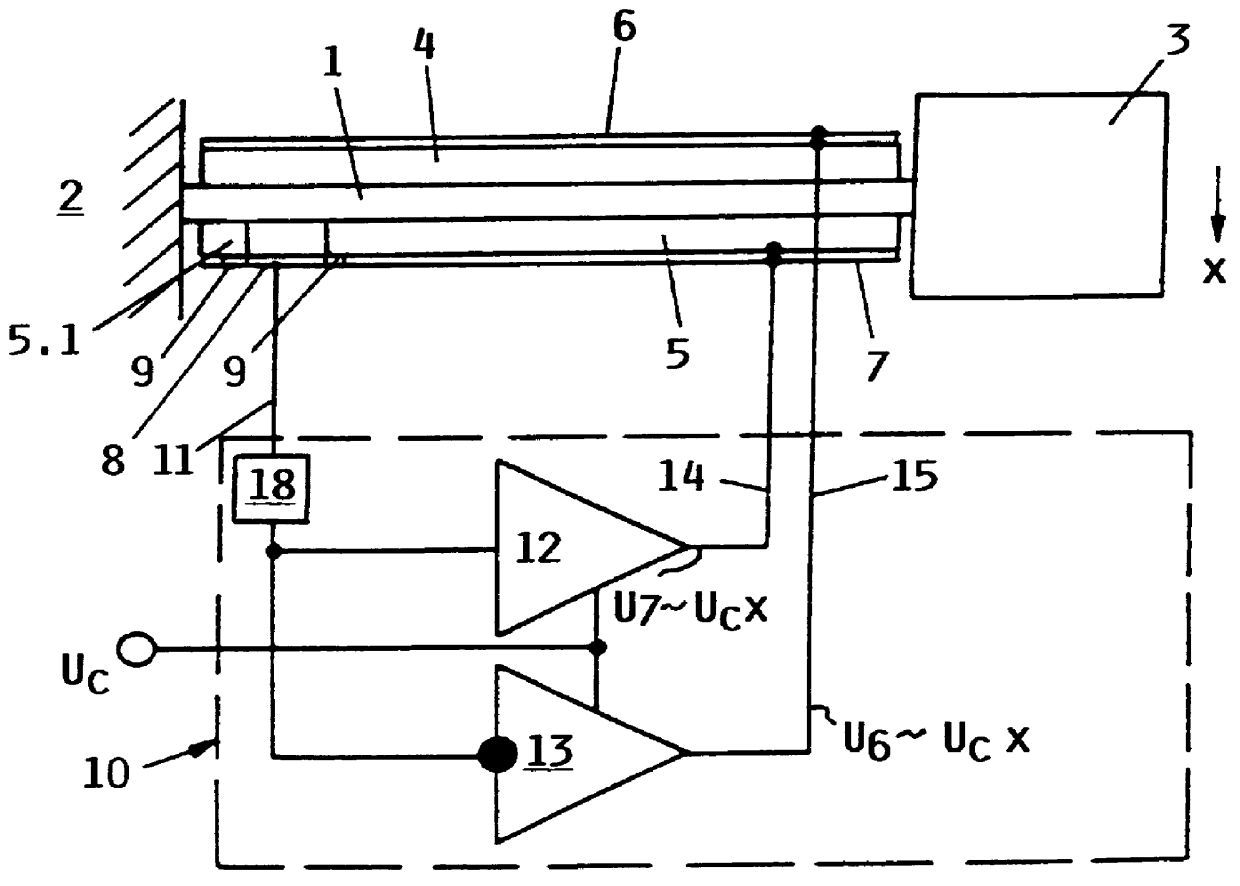
In the example embodiment shown in FIG. 1, the inventive arrangement includes a leaf spring 1 made of spring steel, for example, which is rigidly connected at a first location and particularly at its left end to a structure 2 that is to be vibrationally damped. A massive body 3 providing an inertial mass is mounted on the right, freely vibrating end of the leaf spring 1. As shown, the spring 1 is unsupported between its left end and its right freely vibrating end. The schematic representation of the massive body 3 in FIG. 1 applies both to an actual physical arrangement of a massive body 3 on the free end of the spring 1, and to an arrangement in which the mass of the spring 1 itself is sufficient so that an additional physical massive body 3 can be omitted. In other words, the inertial mass may be incorporated in the spring 1 itself.

Two respective piezoelectric layers or elements 4 and 5 are connected in a force transmitting and electrically conducting manner respectively to the op...


PUM


Abstract

A mechanical resonator has an electronically adjustable resonance frequency and is especially adapted to be used as a tunable vibration absorber. The mechanical resonator includes an inertial mass mounted on a free end of a spring, which is secured at its other end to the structure that is to be vibrationally damped. In order to vary the resonant frequency of the resonator, an electromechanical converter such as a piezoelectric element is connected to the spring and/or the inertial mass, and a displacement and/or acceleration sensor provides a sensor signal that is dependent on the respective displacement and/or acceleration of the spring and/or the inertial mass. An electronic control circuit generates an actuating signal based on the sensor signal. The actuating signal is applied to the electro-mechanical converter, which responsively exerts an adjusting force onto the spring and/or the inertial mass. The control circuit may include one or more variable amplifiers, inverters, and phase shifters, to control the actuating signal such that the adjusting force exerted by the electromechanical converter either counteracts or reinforces the bending force exerted by the inertial mass on the spring. In this manner, the effective total spring constant of the resonator can be increased or decreased relative to the inherent spring constant of the spring, whereby the resonant frequency is adjusted.

Description

FIELD OF THE INVENTIONThe invention relates to a mechanical resonator having a variable resonance frequency, which is especially adapted for use in a vibration absorber or active damper, and which includes an inertial mass and a spring that is secured at at least one end.BACKGROUND INFORMATIONThe resonance frequency of a mechanical resonator, such as a spring-mass vibrator, is essentially determined by the spring stiffness or spring constant of the spring and the size, i.e. mass, of the vibrating inertial mass. It is possible to vary the resonance frequency by correspondingly varying either one or both of these parameters, in order to tune the resonator, for example to match the vibrations of a vibrating body that are to be damped. Such a tuning adjustment is technically simple to carry out, for example by displacing the center of mass of the inertial mass or by moving the fixing location of the spring, but necessarily involves a considerable structural effort and complexity. Namely...

Claims


Application Information

Patent Timeline
IPC IPC(8): B06B1/02F16F7/116F16F15/00F16F7/10G10K11/00G10K11/172H03H9/15
CPCB06B1/0261G10K11/172F16F7/116F16F15/005F16F7/1005B06B2201/20B06B2201/30
Inventor JAENKER, PETERSTREHLOW, HENNING
Owner AIRBUS HELICOPTERS DEUT GMBH
Why Eureka
Try Eureka