Zeros bio-dynamics a zero-emission non-thermal process for cleaning hydrocarbon from soils zeros bio-dynamics

a bio-dynamic and non-thermal technology, applied in the field of decontaminating soil and waste materials, can solve the problems of oil and other hydrocarbon removal, unattractive solution, and very little material conten

a bio-dynamic and non-thermal technology, applied in the field of decontaminating soil and waste materials, can solve the problems of oil and other hydrocarbon removal, unattractive solution, and very little material conten

US6137026AInactive Publication Date: 2000-10-24CLARK STEVE L

Image

  • Zeros bio-dynamics a zero-emission non-thermal process for cleaning hydrocarbon from soils zeros bio-dynamics
  • Zeros bio-dynamics a zero-emission non-thermal process for cleaning hydrocarbon from soils zeros bio-dynamics
  • Zeros bio-dynamics a zero-emission non-thermal process for cleaning hydrocarbon from soils zeros bio-dynamics

Examples


Embodiment Construction

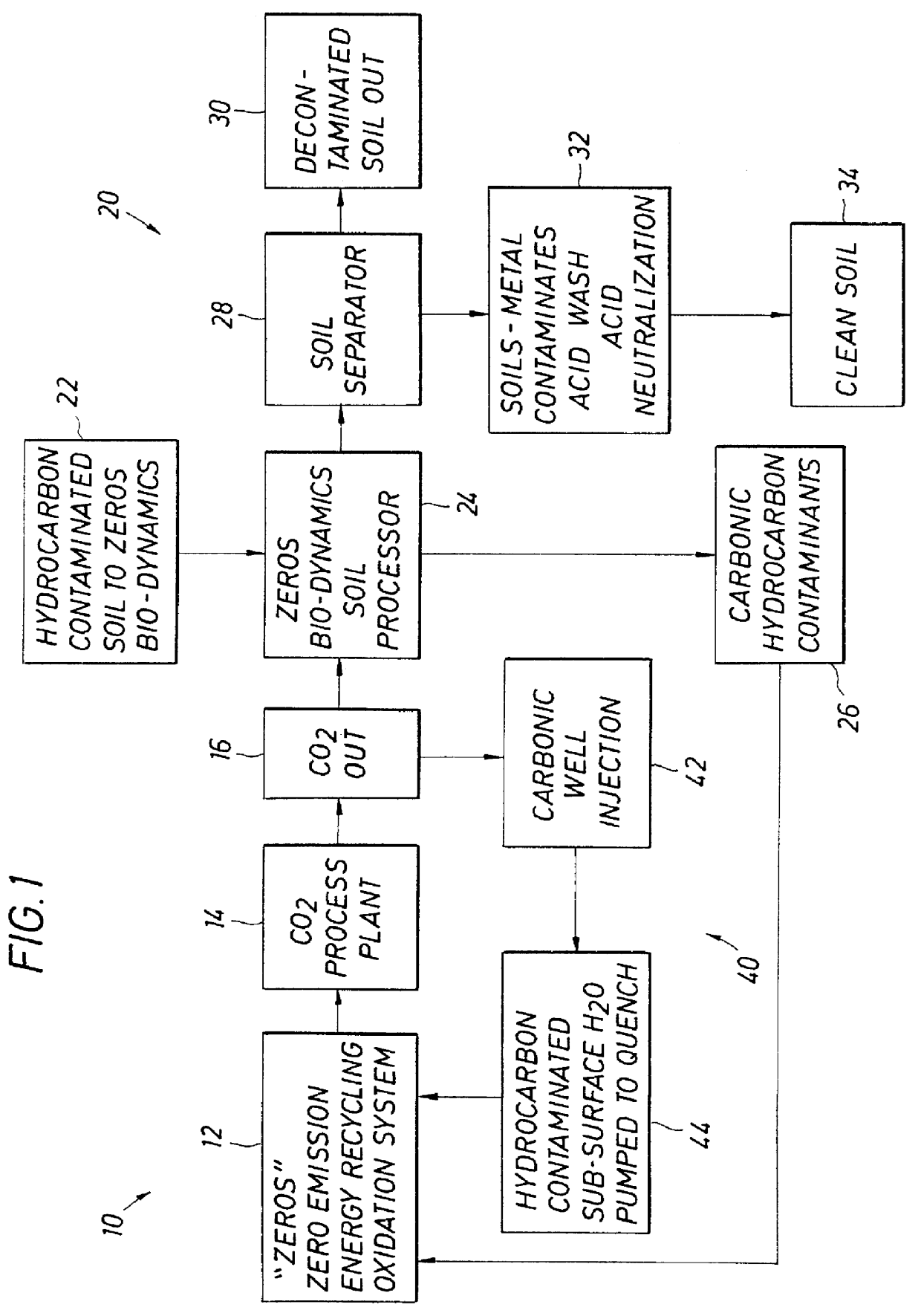
As shown in FIG. 1, the process of the present invention combines a thermal process 10 that includes a combustion step 12 with carbon dioxide recovery 14, with a solvent process 20 for removing hydrocarbons from contaminated soils utilizing carbon dioxide from the thermal process 10 as a solvent. The thermal process 10 includes a combustion step 12 that utilizes oxygen rather than air for oxidation and which utilizes a recycle to increase the combustion efficiency. The carbon dioxide generated in the combustion step is recovered in a carbon dioxide processing step 14. The recovered carbon dioxide is then forwarded in a carbon dioxide distribution step 16 to the solvent process 20. Thermal process 10 is referred to in the figures generally as the ZEROS process. Solvent process 20 is referred to in the figures generally as Bio-dynamics.

The solvent process 20 begins with a step 22 of introducing contaminated soil or other waste material and carbon dioxide from the distribution step 16 ...


PUM


Abstract

A combination of parallel processes is disclosed to provide optimal remediation operations for contaminated soil. Soils with high levels of heavy petroleum hydrocarbons are directed to a thermal process for destruction in a combustion process. Carbon dioxide generated and recovered in the thermal process is employed as a solvent in a solvent process to clean other soils of petroleum hydrocarbons and certain chlorinated hydrocarbon compounds. In the solvent process, contaminated soils are run through a closed soil separator where the soils are washed with carbon dioxide. The carbon dioxide is then dried from the soil and the soil is sent for segregation. Soils with the lightest forms of hydrocarbon contamination (gasoline, etc.) are subjected to a vaporization process utilizing heat energy generated in the thermal process to heat the soil, under a partial vacuum, and the vapors generated are captured, condensed, and recovered as product.

Description

SPECIFICATION1. Field of the InventionThe present invention relates to a process for decontaminating soil and waste materials. More particularly, the present invention relates to a combination of processes including a thermal combustion process, a solvent wash process that utilizes carbon dioxide generated in the thermal process, and a vaporization process that utilizes heat energy generated in the thermal process, which in combination are used to remove volatile organic compounds from soil and other waste which have various levels of contamination.2. Description of the Related ArtFor many years a major problem occurring with the development of industry, in general, and the energy and petrochemical industry, in particular, has been the need to remove the oils and other hydrocarbons that have been spilled from the contaminated soil. The processes of choice have always been traditional thermal combustion processes, but the cost of these processes and the collateral damage that they ca...

Claims


Application Information

Patent Timeline
24 Oct 2000
Publication
US6137026A
IPC
A62D3/00; B09C1/06; B09C1/00
CPC
B09B3/0091; B09C1/06; B09C1/005; Y02W30/20; B09B3/45
Inventors
CLARK, STEVE L.