

Method of manufacturing porous anodized alumina film
a technology film, which is applied in the field of manufacturing methods of porous anodized alumina films, can solve the problems that the porous anodized alumina film formed by the conventional technique does not have a satisfactory regularity
- Summary
- Abstract
- Description
- Claims
- Application Information
AI Technical Summary
Problems solved by technology
Method used
Image

Examples
first embodiment
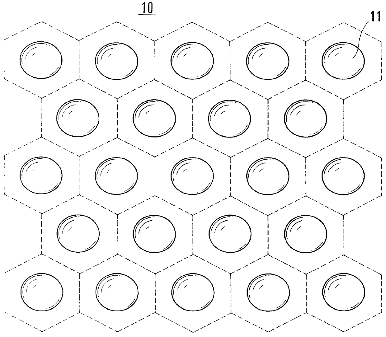
FIG. 1 is a plan view of an aluminum plate used in the first embodiment.
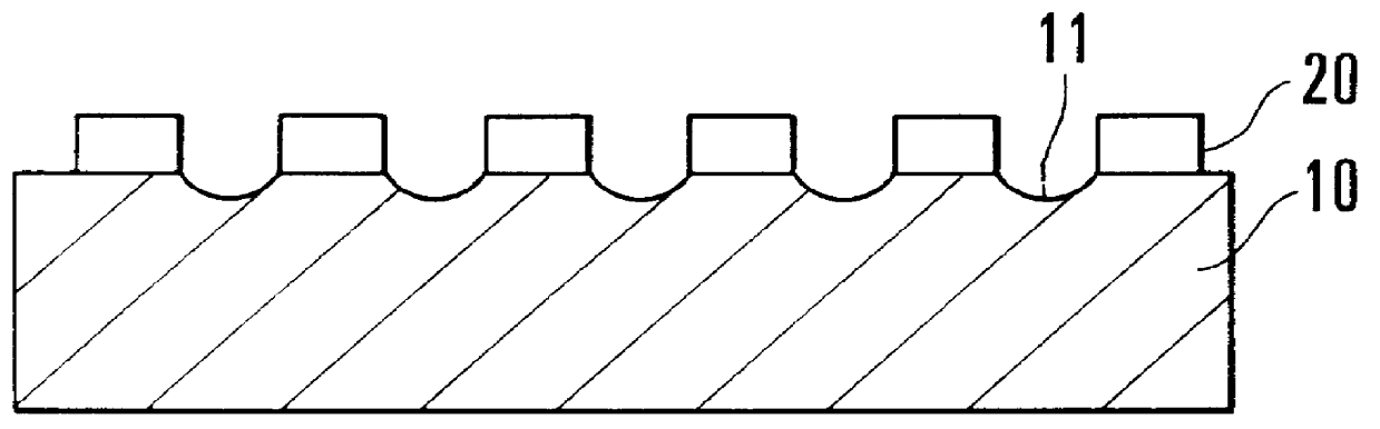
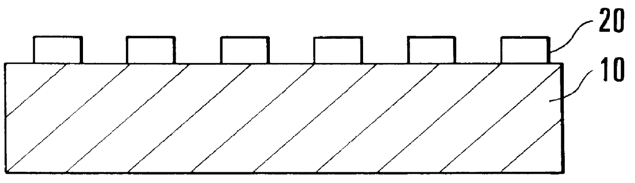
A plurality of fine recesses 11 are formed in the surface of an aluminum plate 10 in advance. These recesses 11 have an interval and array corresponding to those of pores to be formed by anodizing. In this embodiment, to maximize the regularity of pores to be formed by anodizing, recesses around each recess are arrayed in a regular hexagon.
As the aluminum plate, an aluminum plate with high purity is used. The purity is preferably 99.99% or more.
The surface of the aluminum plate 10 is polished to a mirror surface by an appropriate method, thereby smoothing the aluminum plate surface before formation of the recesses 11. More specifically, electropolishing can be performed using the aluminum plate 10 as an anode in an appropriate electrolyte. As an example of such electropolishing, a bath prepared by mixing perchloric acid and ethanol at a ratio of 1:4 is used as the electrolyte, the aluminum plate 10 is used as th...
second embodiment
The second embodiment of the present invention will be described next with reference to FIG. 5.
In this embodiment, to form a plurality of recesses on the surface of an aluminum plate, a mask is formed not by photolithography but using polystyrene balls, and etching is performed.
As in the above-described first embodiment, a surface of an aluminum plate 50 to be anodized is mirror-polished, as in the above-described first embodiment, and polystyrene balls 52 are two-dimensionally packed on the surface of the aluminum plate 50 to form a film in a tight contact state (FIG. 5(a)).
While using the polystyrene balls 52 in the tight contact state as a mask, e.g., SiO.sub.2 is excessively deposited under an appropriate pressure. SiO.sub.2 surrounds the balls to form an SiO.sub.2 mask having openings corresponding to the polystyrene balls 52 on the surface of the aluminum plate 50 (FIG. 5(b)).
When the aluminum plate 50 is etched using the resultant SiO.sub.2 film as a mask, a surface structure...
third embodiment
The pore interval of the porous anodized alumina film obtained in the above-described first embodiment is as small as about 0.1 .mu.m. To artificially and regularly form such fine recesses in the aluminum plate surface, a high-resolution micropatterning technique is required. When electron beam lithography or X-ray lithography is used, the microfine recesses 11 can be formed in the aluminum plate 10 (FIG. 1). However, it is not economical to apply such an advanced fabrication technique every time porous anodized alumina is formed, which may impose limitations on the application purpose of the porous anodized alumina film of the present invention.
As a characteristic feature of the porous anodized alumina film forming method according to the third embodiment, a plurality of recesses are formed in an aluninum plate surface by pressing a substrate with a plurality of projections on its surface against the aluminum plate surface, i.e., transferring a mother pattern onto the aluminum plat...
PUM
| Property | Measurement | Unit |
|---|---|---|
| Electric potential / voltage | aaaaa | aaaaa |
| Electric potential / voltage | aaaaa | aaaaa |
| Piezoelectric constant | aaaaa | aaaaa |
Abstract
Description
Claims
Application Information