Structure of rotor for generators and method of manufacturing the same rotor

a technology of rotor and rotor body, which is applied in the direction of magnetic circuits, magnetic circuits, rotating parts, etc., which can solve the problems of low processability, increased rotor manufacturing cost, and difficulty in grinding a permanent magnet comprising such a sintered body with a grinding tool

Inactive Publication Date: 2000-11-07
ISUZU MOTORS LTD
View PDF15 Cites 65 Cited by
  • Summary
  • Abstract
  • Description
  • Claims
  • Application Information

AI Technical Summary

Problems solved by technology

However, it is difficult to grind a permanent magnet comprising such a sintered body by a grinding tool due to the material of the permanent magnet.
This causes the processing time for forming a permanent magnet into a rotor, a manday for subjecting a permanent magnet to various steps from a grinding step to a precision processing step and the rotor manufacturing cost to increase.
A permanent magnet comprises a sintered body of an alloy of rare earth metals, and has a low processability.
Since this sintered body is ground slowly so as to prevent a bit from being damaged, the processing cost increases greatly as compared with the material cost, so that the manufacturing cost becomes high.
However, it is difficult and takes a long time to grind the outer and inner circumferential surfaces of a sintered body of a permanent magnet, and this causes the manufacturing cost to increase greatly.
It is difficult to form a permanent magnet cylindrically to a large diameter, and a permanent magnet into a large-diameter rotor.
Consequently, large output generation cannot be expected as long as a permanent magnet is used as a rotor.
When a permanent magnet is divided into segment members, in to what type of a structure should these members be combined is an issue.
When a rotor in a generator is rotated at a high speed, a high output is obtained, and this poses an issue as to what structure is required for a rotor having smaller weight, a higher rigidity and a higher resistance to a high-speed rotation.
Consequently, when the dimensions of the rotor increases, the cost of regenerating the permanent magnet increases correspondingly, and a loss becomes larger.
Therefore, when a rotor is formed of a permanent magnet, it is necessary that the rotor be cooled so that demagnetization does not occur in the permanent magnet, and developing the techniques for cooling a rotor effectively is an issue encountered in the prior art.

Method used


Image

  • Structure of rotor for generators and method of manufacturing the same rotor
  • Structure of rotor for generators and method of manufacturing the same rotor
  • Structure of rotor for generators and method of manufacturing the same rotor

Examples


Embodiment Construction

The embodiments of the structure of a rotor for generators according to the present invention and a method of manufacturing the same will now be described with reference to the drawings.

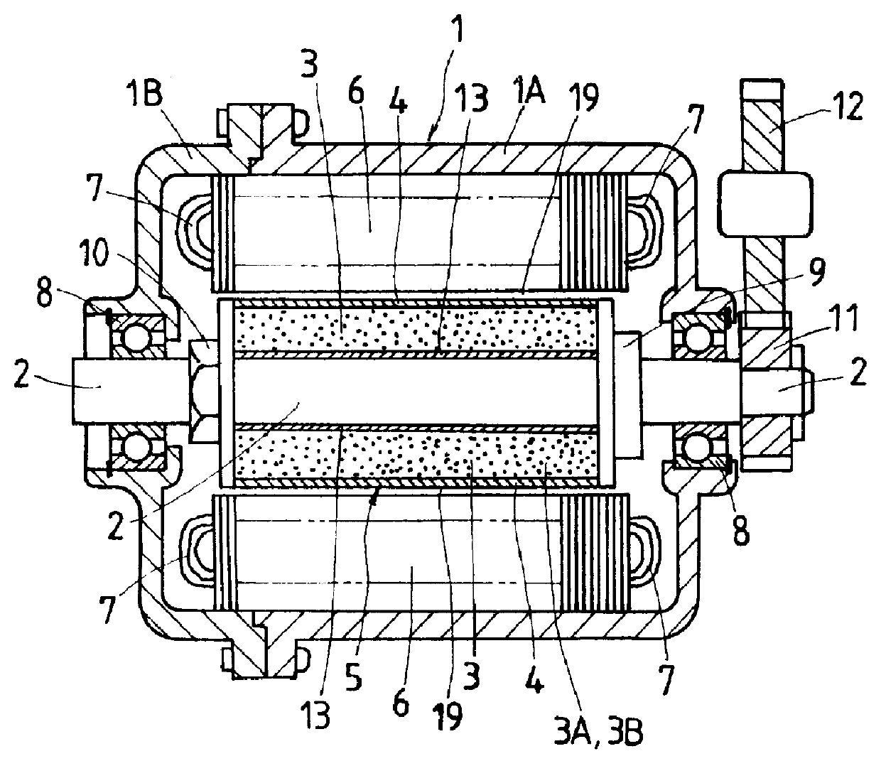
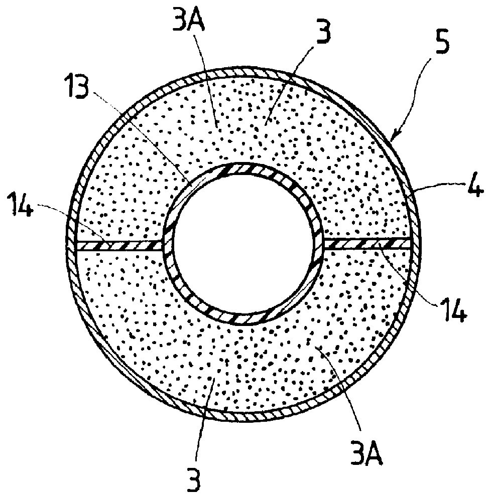
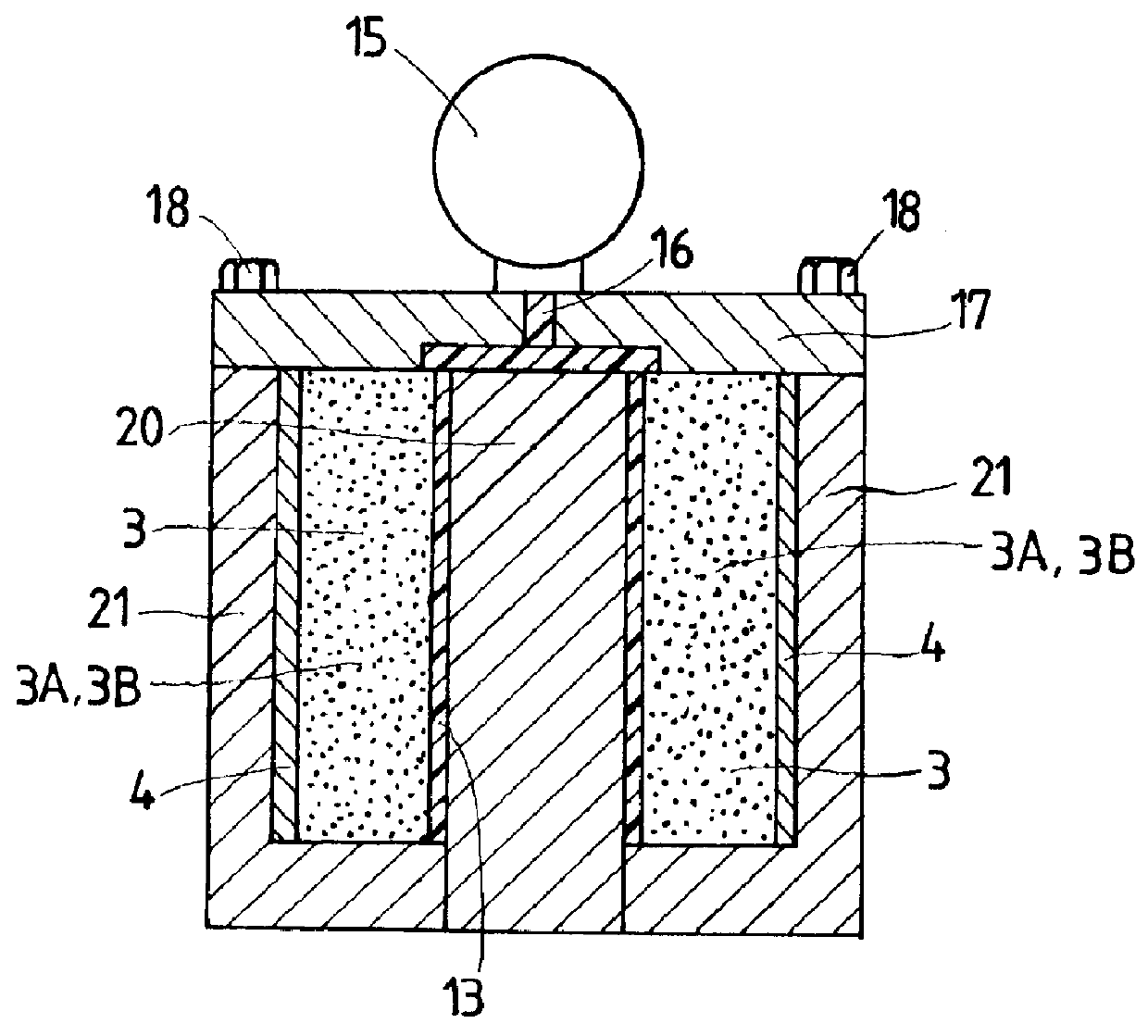
First, a first example of a generator in which the rotor according to the present invention is incorporated will be described with reference to FIGS. 1-4.

A first example of a generator in which the structure of a rotor is incorporated has mainly a rotary shaft 2 supported rotatably on a case 1, which comprises a pair of housings 1A, 1B, via a pair of bearings 8, a rotor 5 mounted fixedly on the rotary shaft 2, and a stator 6 provided around an outer circumference of the rotor 5 and fixed to the case 1 with a clearance formed between the stator 6 and rotor 5. The rotor 5 is engaged at one end thereof with a stopper 9 mounted on the rotary shaft 2, and fixed at the other end to the rotary shaft 2 by a locking nut 10 screwed to the rotary shaft 2. A transmission gear 11 is mounted fixedly on one end of ...


PUM


Abstract

The present invention provides a structure of a rotor for a generator in which a rotor capable of being ground very easily with a high accuracy is incorporated. This structure of a rotor comprises a rotor mounted fixedly on a rotary shaft supported rotatably on housings. The rotor comprises cylindrically arranged members in which segmental members of permanent magnets are assembled together cylindrically, and an outer cylinder provided on an outer circumference of the cylindrically arranged members and comprising windings or woven cloths of fibers. A resin material capable of being ground is packed in clearances between the cylindrically arranged members and outer cylinder and in the clearances in the outer cylinder.

Description

1. Field of the InventionThis invention relates to a structure of a rotor for a generator comprising a rotor formed of a permanent magnet mounted on a rotary shaft, and a stator disposed around an outer circumference of the rotor; and a method of manufacturing the rotor.2. Description of the Prior ArtAs the performance of a permanent magnet has been improved, the opportunities in which a permanent magnet is used as a rotor of a generator have increased. A generator-motor using a permanent magnet as a rotor obtains high generating and power efficiencies, and can be formed to a simple structure. Owing to these characteristics, such a generator-motor has recently come to be used much in industrial machines and tools.When a rotational frequency of a rotor in a conventional generator-motor increases as a voltage and an amperage increase, a large centrifugal force occurs in the rotor, so that the rotor is required to withstand the centrifugal force. Therefore, an outer circumference of th...

Claims


Application Information

Patent Timeline
Patent Type & Authority Patents(United States)
IPC IPC(8): H02K9/06H02K9/04H02K15/03H02K1/32H02K1/27H02K1/00H02K1/02
CPCH02K1/278H02K15/03H02K9/06H02K1/32H02K1/02
Inventor KAWAMURA, HIDEO
Owner ISUZU MOTORS LTD
Why Eureka
Try Eureka