

Spatial magnetic interrogation
a magnetic interrogation and spatial technology, applied in the field of spatial magnetic interrogation, can solve the problem of real drawback of barcodes, the need for line-of-sight between the reader and the tag
- Summary
- Abstract
- Description
- Claims
- Application Information
AI Technical Summary
Benefits of technology
Problems solved by technology
Method used
Image

Examples
Embodiment Construction
Use of Spatial Magnetic Scanning for Position Sensing
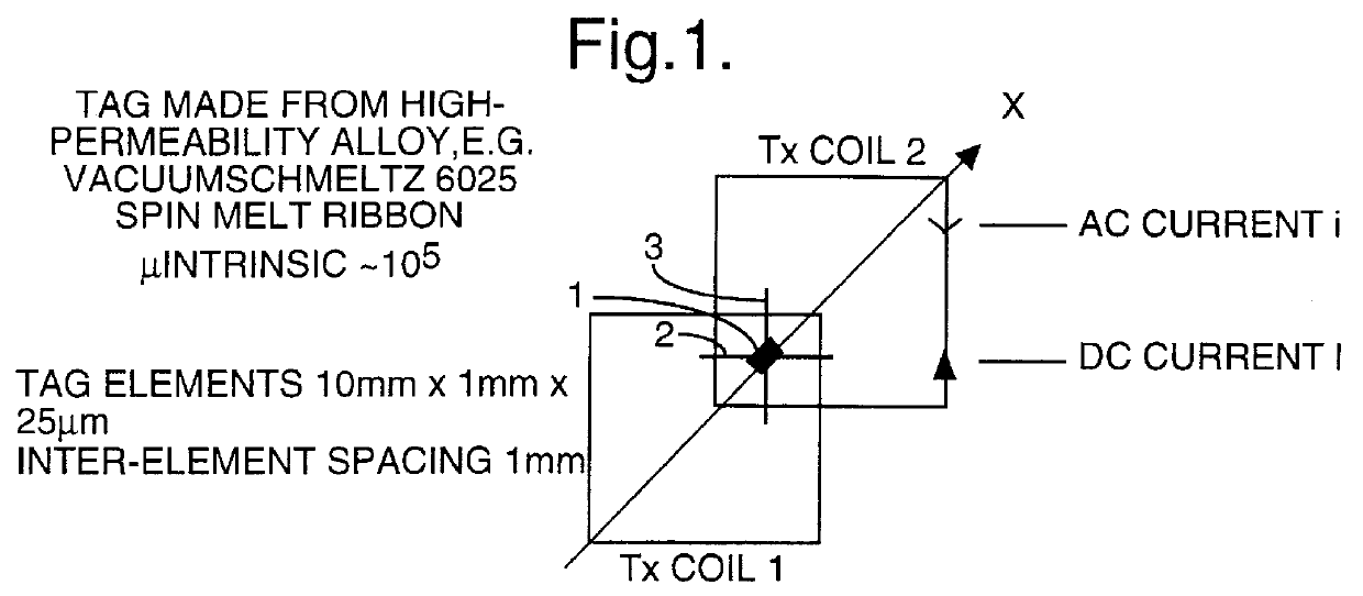
In addition to interrogating space to read data tags, this new technique of moving planes of zero field through space (or moving things through the planes) can be used to provide accurate location information for small items of high permeability magnetic material.
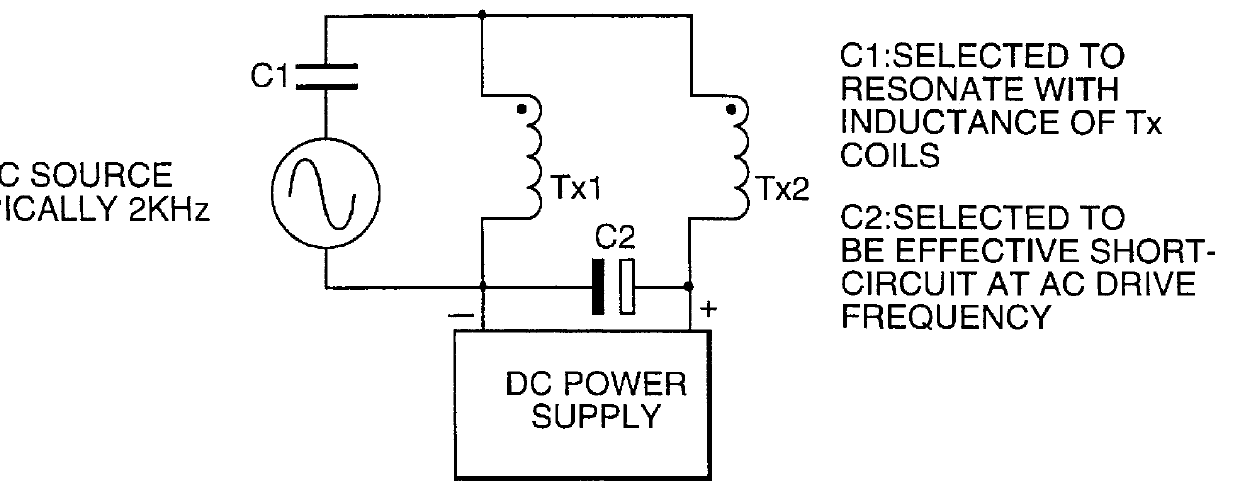
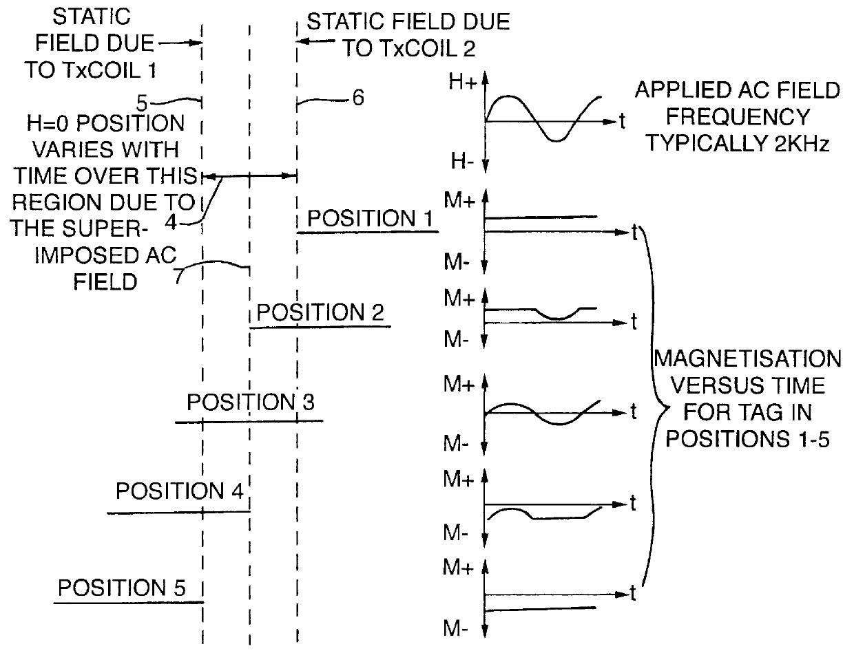
Thus, according to another aspect, the invention provides a method of determining the precise location of an object, characterised in that the method comprises: (a) securing to the object a small piece of a magnetic material which is of high magnetic permeability; (b) applying to the region in which said object is located a magnetic field comprising two opposed field components, generated by magnetic field sources, which result in a null field at a position intermediate said magnetic field sources; (c) applying a low amplitude, high frequency interrogating field to said region; (d) causing the position of the null field to sweep slowly back and forth over a predetermined ...
PUM
 Abstract
Description
Claims
Application Information