Disinfection of dead-ended lines in medical instruments

a technology of dead-end lines and medical instruments, applied in the field of medical instruments, can solve the problems of insufficient rinsing of fluid segments, removing all chemical agents, and no way to flow water through tube segments, and maintain a constant high-level disinfection temperatur

Inactive Publication Date: 2000-11-28
BAXTER INT INC +2
View PDF12 Cites 90 Cited by
  • Summary
  • Abstract
  • Description
  • Claims
  • Application Information

AI Technical Summary

Problems solved by technology

For example, if chemical disinfection agents are used then there is a problem of adequately rinsing the fluid segment and removing all of the chemical agents.
If hot

Method used


Image

  • Disinfection of dead-ended lines in medical instruments
  • Disinfection of dead-ended lines in medical instruments
  • Disinfection of dead-ended lines in medical instruments

Examples


Embodiment Construction

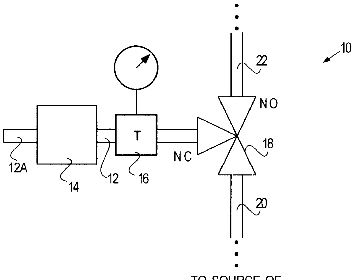
Referring now to FIG. 1, a representative medical instrument 10, such as a dialysis machine (the details and type of which are not important) includes a dead-ended line 12 terminating in pressure transducer isolator, or any other piece of equipment 14, the details of which are not important. The line 12 is considered "dead ended" because although water or other fluid can flow into the line 12, it is not in a loop or circuit such that fluid can flow in one end and out the other. The fluid can be introduced or withdrawn from the line 12 by using positive pressure and pumping the fluid into the line 12 via a line 20 and operating a valve 18 such that the normally closed port NC is opened. Fluid is withdrawn from line 12 by creating negative pressure or vacuum in line 20 with port NC of valve 18 open. Alternatively, pressure adjustment apparatus (such as a pump) could be placed behind the element 14 in line 12A. The pump would draw fluid from the line 20 into the line 12 with negative p...


PUM

PropertyMeasurementUnit
Timeaaaaaaaaaa
Timeaaaaaaaaaa
Timeaaaaaaaaaa

Abstract

A method of disinfection of a dead-ended fluid line in a medical instrument such as a dialysis machine is described. The method comprises introducing a heated fluid into the fluid line, allowing the fluid to remain in the line for an experimentally determined optimal dwell period, removing the fluid from the fluid line, and then repeating the cycle for a time period sufficient to achieve a disinfection of the fluid line. The optimum dwell period and frequency for exchanging the heated fluid is determined so that the heated fluid is left resident in the line to exert a cidal effect but not so long that the it cools to the point of being ineffective, nor changed so frequently that that the time spent with no hot water resident in the line begins to detract (e.g., unduly prolong) the disinfection process. A representative cycle is introducing water at a temperature of about 85 degrees C, allowing it to reside in the fluid line for about 10 seconds, withdrawing the water, and then reintroducing water at 85 degrees C. The process continues for 1-2 hours. Variation from the representative cycle will be expected based on parameters such as the degree to which disinfection is to be achieved, the length and diameter of the fluid line, the temperature of the fluid, the ambient temperature, the presence of elements in the fluid line that contribute to heat loss, the material used for fluid line tubing, and whether the fluid comprises water or a disinfection solution such as a dilute citric acid solution. The optimum dwell period and frequency of the cycles can be determined experimentally from the teachings described herein.

Description

1. Field of the InventionThis invention relates generally to the field of medical instruments such as dialysis machines, and more particularly to the process of disinfection of such instruments. Even more particularly, the invention relates to a method for disinfecting a line that is dead-ended in a medical instrument.2. Description of Related ArtDialysis machines are machines that are used for treating patients suffering from inadequate kidney function. The machines typically have an extracorporeal blood circulation circuit that withdraws blood from the patient into an arterial line, circulates the blood to a dialyzer filter, and then returns the blood back to the patient via a venous line. The dialyzer filter is a semi-permeable membrane that separates the patient's blood from a dialysate solution that is circulated on the other side of the membrane. Blood-borne toxins and excess water are removed from the patient's blood though the membrane and are carried away in the dialysate s...

Claims


Application Information

Patent Timeline
IPC IPC(8): A61L2/04A61L2/18A61M1/16B01D61/12B01D65/10B01D65/02B01D61/02B01D65/00B01D61/04C02F1/44A61M1/34
CPCA61L2/04B01D61/027A61M1/1686B01D61/02B01D61/04B01D61/12B01D65/022B01D65/10C02F1/441A61L2/18B01D61/025A61M1/3434A61M1/3431B01D65/027A61M1/165A61M1/1668A61M2205/505B01D2311/04B01D2321/08B01D2311/10B01D2311/103B01D2311/12
Inventor KENLEY, RODNEY S.WIEBENSON, DEREK
Owner BAXTER INT INC
Why Eureka
Try Eureka