Internal combustion engine with at least one injection device per cylinder

a technology of injection device and internal combustion engine, which is applied in the direction of combustion engine, machine/engine, cylinder, etc., can solve the problems of limited effect of injection system, inability to use all injection system measures, and increased tension of cylinder head

Inactive Publication Date: 2000-12-12
AVL LIST GMBH
View PDF12 Cites 13 Cited by
  • Summary
  • Abstract
  • Description
  • Claims
  • Application Information

AI Technical Summary

Benefits of technology

According to the invention this object is achieved by configuring the area around the nozzle of the injection device as a flow-directing surface for a swirl and / or tumble flow. By designing the area around the injector nozzle as a flow-directing surface, the primary flow in the cylinder is directed such that the last portion of fuel leaving the injection device is quickly carried from the injector to the ignition site, the flow-directing surfaces assisting the swirl or tumble movement. Due to the high flow velocities in the nozzle region the fuel is rapidly advanced from the nozzle towards the ignition site, such that fewer deposits will be able to form. In addition, charge stratification is improved in the combustion chamber, especially towards the end of the injection period.
The invention preferably provides that the flow-directing surface is formed by the top surface of the combustion chamber and / or the top surface of a piston. In this way the flow of charge may be specifically directed towards the ignition site, for example, in the center of the combustion chamber. In addition, the primary flow will produce a cooling effect.
It is provided in a preferred variant that the flow-directing surface be formed, at least partially, by a recess. It could equally be provided that the flow-directing surface be formed, at least partially, by a guide rib. The flow-directing surfaces formed in this way are easy to manufacture and will have no adverse effects on the inhomogeneous combustion process.
Another measure aimed at reducing the build-up of carbon deposits is constituted by giving the flow-directing surface a concave shape, its largest curvature being in a flow exit area and / or in the area around the injector nozzle.

Problems solved by technology

The disadvantage of this procedure is that the cylinder head will be subject to additional tensions.
Because of the wide thermal operating range of an internal combustion engine for motor vehicles, and as fuel metering is often effected in the front part of the injection device, this measure cannot be employed with all injection systems.
The effect of this measure is limited to a narrow range directly before top dead center of the piston, however.
Combustion will be impaired and fuel consumption and CH emissions will rise.

Method used


Image

  • Internal combustion engine with at least one injection device per cylinder
  • Internal combustion engine with at least one injection device per cylinder
  • Internal combustion engine with at least one injection device per cylinder

Examples


Embodiment Construction

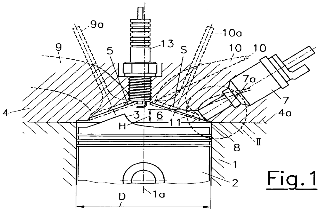
FIG. 1 shows a cylinder 1 of an internal combustion engine, in which is positioned a reciprocating piston 2. The top surface 3 of the piston 2 and the roof-shaped combustion chamber top face 5 formed by the cylinder head 4 confine a combustion chamber 6 entered by an injection device 7, whose nozzle 8 is positioned near the periphery of the combustion chamber top face 5. Charge exchange ports 9 and 10 for supplying fresh air and expelling exhaust gas also open into the combustion chamber 6. The corresponding valves for the intake and exhaust streams bear reference numerals 9a and 10a.

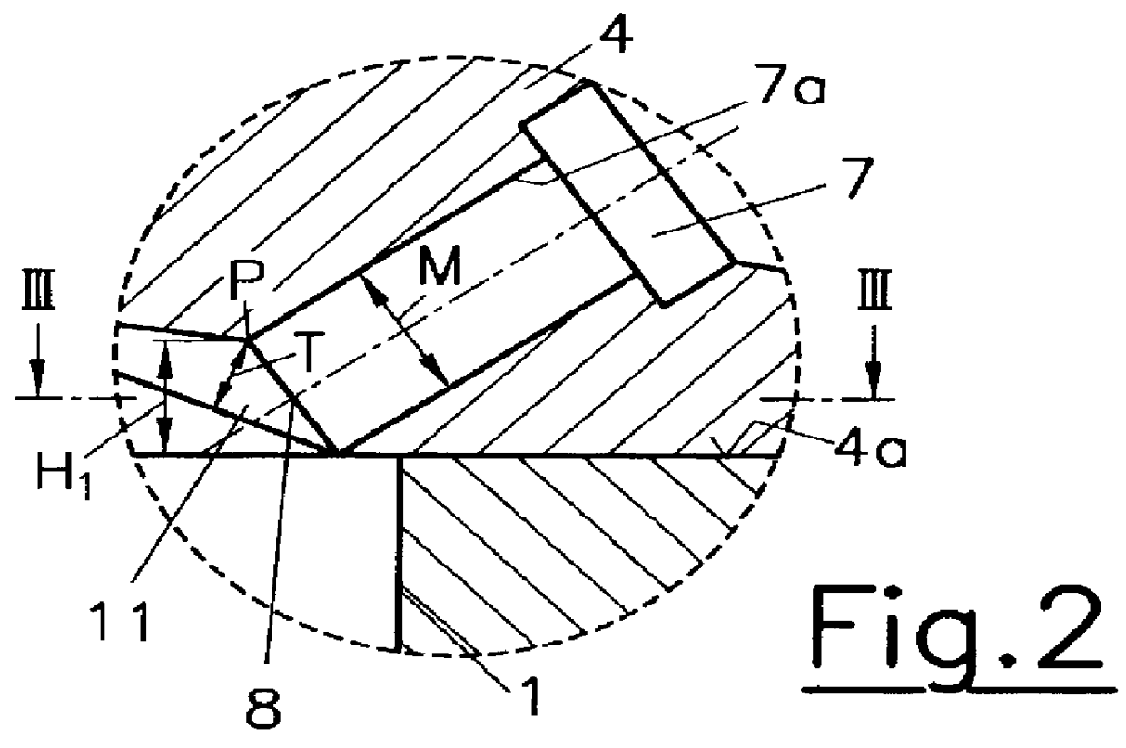
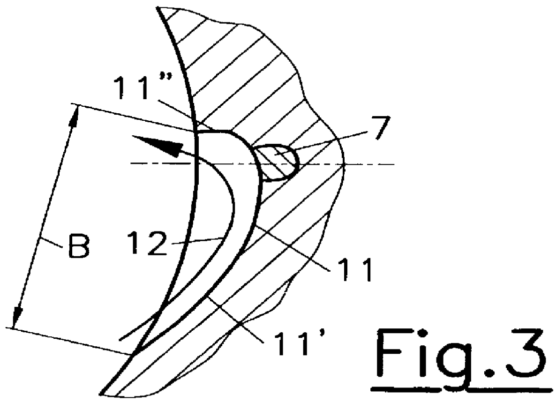
In the region of the nozzle 8 of the injection device 7 flow-directing surfaces 11 are provided for assisting a swirl flow indicated by arrows 12, as is shown in FIGS. 2 to 4. The term swirl flow denotes a motion about the cylinder axis 1a. The flow-directing surfaces 11 are configured, at least partially, as recesses in the combustion chamber top face 5. The flow-directing surfaces 11 presented in FIGS...


PUM


Abstract

In an internal combustion engine with at least one injection device per cylinder for direct fuel injection into a combustion chamber, the injector nozzle is located in a top surface of the combustion chamber, which is formed in the cylinder head. In order to reduce the build-up of deposits and carbon residues in the region where the injection device enters the combustion chamber, the area around the injector nozzle is configured as a flow-directing surface for a swirl and / or tumble flow.

Description

This invention relates to an internal combustion engine with at least one injection device per cylinder for direct fuel injection into a combustion chamber, the nozzle of the injection device being positioned in a combustion chamber top face formed in the cylinder head.DESCRIPTION OF THE PRIOR ARTIn direct-injection internal combustion engines, in particular of the spark-ignition type, the formation of deposits and carbon residues in the area of the injector nozzle may significantly change the characteristic of the injection jet. This may be prevented by keeping the temperature at the injector orifice below carbonization temperature by thermally coupling the injection device to the cylinder head. In such instance the front part of the injection device is mechanically coupled to the cylinder head in order to obtain proper heat transfer from the injector into the cylinder head. The disadvantage of this procedure is that the cylinder head will be subject to additional tensions.Another ...

Claims


Application Information

Patent Timeline
Patent Type & Authority Patents(United States)
IPC IPC(8): F02B23/10F02F1/42F02B77/04F02F3/28F02B75/00F02F1/24F02B75/12F02F3/26
CPCF02B23/104F02B77/04F02F3/28F02F1/4214F02B2023/106F02B2023/108F02B2075/125F02B2275/48Y02T10/123F02F3/26F02F2001/241F02F2001/245Y02T10/125Y02T10/146Y02T10/12
Inventor PIOCK, WALTERWIRTH, MARTIN
Owner AVL LIST GMBH
Why Eureka
Try Eureka