Laser lighting system
- Summary
- Abstract
- Description
- Claims
- Application Information
AI Technical Summary
Benefits of technology
Problems solved by technology
Method used
Image

Examples
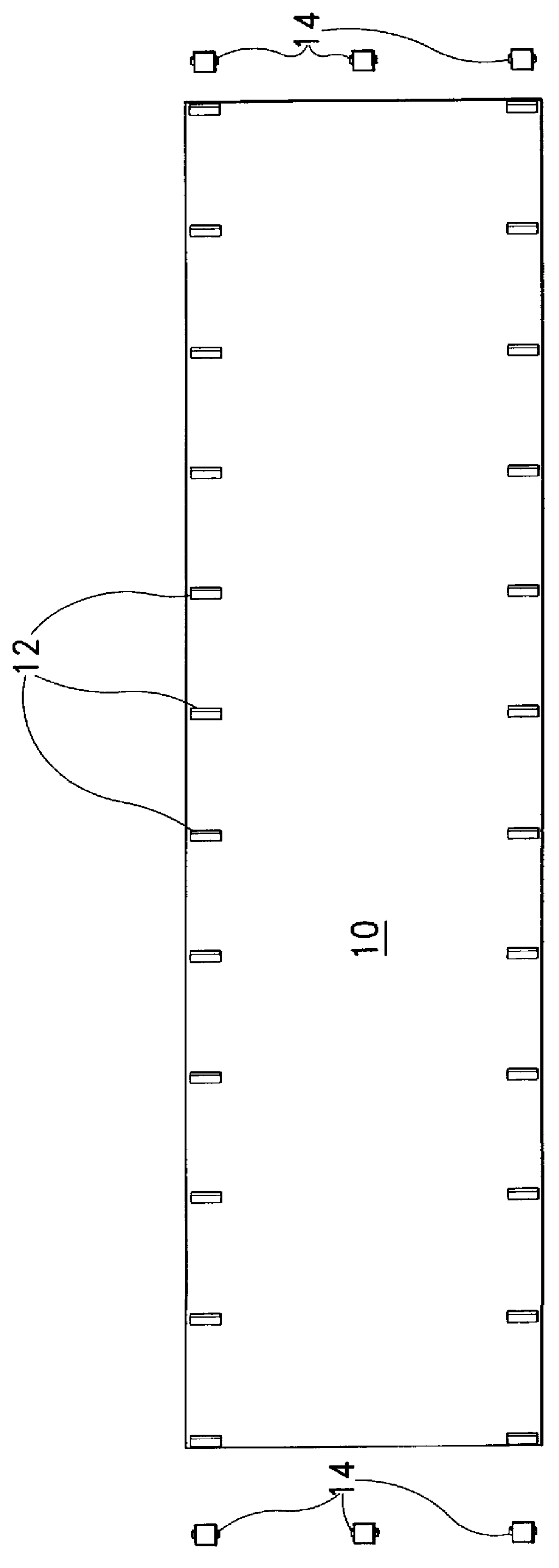
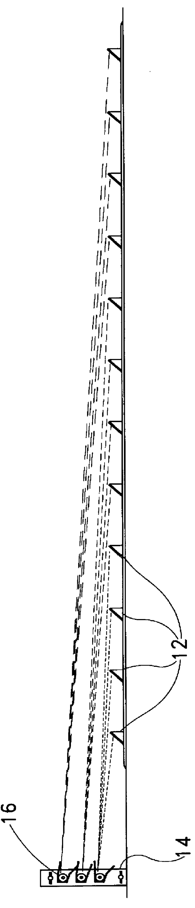
case 130
contains a laser 132 including a lens 134 for directing the generated laser light. The lens 134 is a line generating optic comprising a glass plano-convex cylindrical lens having an aspherical cylindrical convex surface which is critical for generating a laser line which is uniformally illuminated from end to end. The laser 132 is powered by means of switch means 118 which selectively energizes the laser 132 via wiring 128 which provides power from switch means 118 delivered by the batteries. The projected laser line is emitted through the rear end of case 130 through a small opening 138.
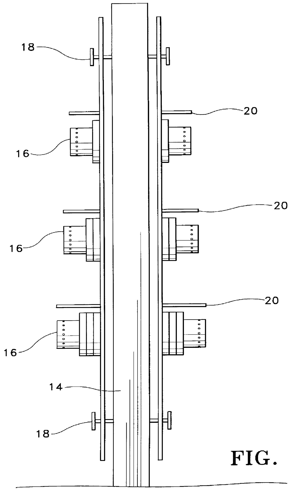
FIG. 11 shows a handheld laser lighting unit 140 for use in search and rescue operations. The laser lighting unit 140 includes a case 142 containing a green laser 148 and a red laser 152 that each include a line generating optic lens 150 and 154 for directing the generated laser light. The lenses 150 and 154 each comprise a glass plano-convex cylindrical lens having an aspherical cylindrical convex ...
PUM
 Abstract
Description
Claims
Application Information
 - R&D
- Intellectual Property
- Life Sciences
- Materials
- Tech Scout
- Unparalleled Data Quality
- Higher Quality Content
- 60% Fewer Hallucinations
Browse by: Latest US Patents, China's latest patents, Technical Efficacy Thesaurus, Application Domain, Technology Topic, Popular Technical Reports.
© 2025 PatSnap. All rights reserved.Legal|Privacy policy|Modern Slavery Act Transparency Statement|Sitemap|About US| Contact US: help@patsnap.com