Bistable microactuator with coupled membranes

a micro-actuator and coupled membrane technology, applied in electrostatic generators/motors, chemical vapor deposition coatings, decorative arts, etc., can solve the problems of low range of electrostatics, rather specific technologies, and not general-purpose use, and achieve the effect of improving pneumatic or liquid coupling

Inactive Publication Date: 2001-01-02
FRAUNHOFER GESELLSCHAFT ZUR FOERDERUNG DER ANGEWANDTEN FORSCHUNG EV
View PDF16 Cites 185 Cited by
  • Summary
  • Abstract
  • Description
  • Claims
  • Application Information

AI Technical Summary

Benefits of technology

The actuator module is designed to achieve a deflection of .+-.10 .mu.m and can be integrated in a microvalve for controlling the flow of fluids. With completed actuator modules the electrostatic driving principle is used in examples for a valve application, e.g. an on/off valve or a multi-way-valve, a switch application, e.g. an on/off-switch or a changeover swi

Problems solved by technology

A drawback of electrostatics is its low range.
These technologi

Method used


Image

  • Bistable microactuator with coupled membranes
  • Bistable microactuator with coupled membranes
  • Bistable microactuator with coupled membranes

Examples


Embodiment Construction

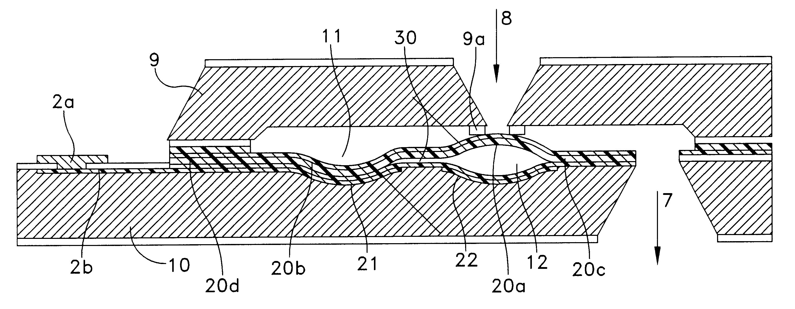
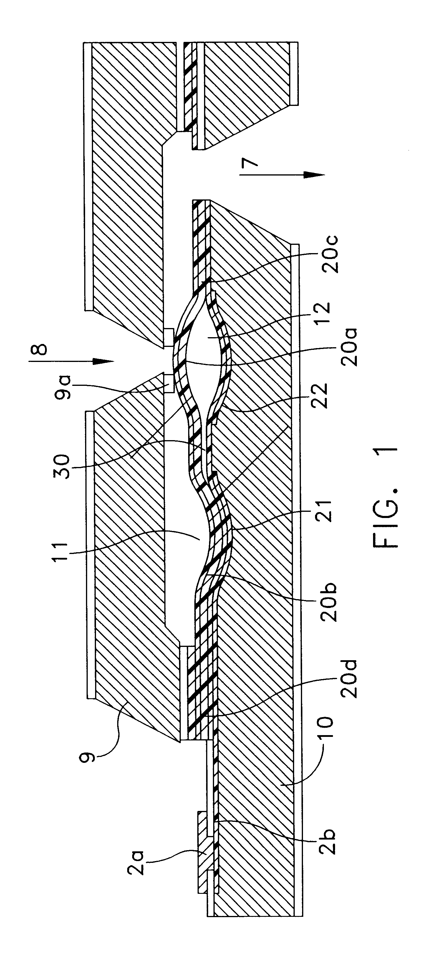
FIG. 1 shows a schematic cross-section of a first example of a valve with buckling membranes.

FIG. 2 shows an exploded view of the bistable microvalve.

FIG. 2a is its side view. The manufacturing of FIGS. 6 and 7 leads to the FIG. 2a embodiment.

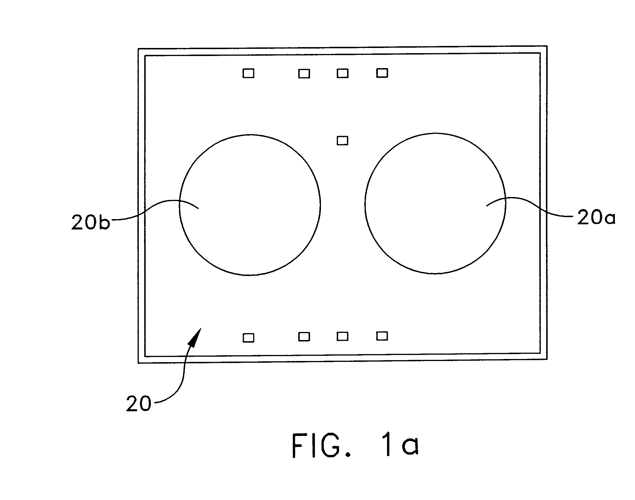
The lower active chip 100 of the valve contains two silicon membranes 20b, 20b, which are buckling due to intrinsic compressive stress. The cavities 11, 12 below the closely spaced membranes 20a, 20b are air-filled and connected by a channel 30. Thus, the membranes are pneumatically coupled in order to operate in counteraction. Each membrane section 20a, 20b can be switched down by electrostatic forces using an underlying driving electrode 21 and 22 as can also be seen from FIG. 8, which displays the same principle of membrane buckling in a multi-way application (3 / 2 way valve). By switching one membrane down the air is pressed through the channel 30 and pushes the second membrane up. The use of two coupled membranes has the advantage that the ...


PUM

PropertyMeasurementUnit
Lengthaaaaaaaaaa
Forceaaaaaaaaaa
Shapeaaaaaaaaaa

Abstract

A bistable electrostatic actuator with pneumatic or liquid coupling. The actuator has enclosed metallic electrodes. It can be used for a microvalve or micropump. The actuator has buckled membrane sections in pairs and curved substrate electrodes, locally associated with said membrane sections.

Description

BACKGROUND OF THE INVENTION1. Field of the InventionThe invention concerns a bistable electrostatic actuator with pneumatic or liquid coupling.2. Prior ArtFrom power and safety considerations mechanically bistable acuators are of considerable importance. However, only a few bistable microactuators fabricated in silicon technology have been reported.sup.1,2,3. Due to the low power consumption electrostatic drives are often preferred to electromagnetic and thermomechanic actuators. A drawback of electrostatics is its low range. High voltages are needed to achieve large deflections. Different concepts have been reported to produce non-planar driving electrodes.sup.4,5,6,7. These technologies are however rather specific and not for general-purpose use. Further prior art is sensitive, since electrodes are free to the environment, e.g. particles. This can be improved, when enclosed electrodes, separated from the gaseous or liquid medium are formed.sup.4.SUMMARY OF THE INVENTIONOne of the ...

Claims


Application Information

Patent Timeline
IPC IPC(8): F04B43/02F04B43/04F15C5/00H01H59/00H02N1/00B81C1/00B81B3/00F15C3/04F16K99/00H01L41/22H01L41/312
CPCF04B43/043F15C5/00F16K99/0001F16K99/0015F16K99/0051H01H59/0009H02N1/006F16K2099/0069F16K2099/0074F16K2099/008G11C23/00H01H2001/0042
Inventor QUENZER, HANS JOACHIMWAGNER, BERND
Owner FRAUNHOFER GESELLSCHAFT ZUR FOERDERUNG DER ANGEWANDTEN FORSCHUNG EV
Why Eureka
Try Eureka