In situ micromachined mixer for microfluidic analytical systems

a microfluidic and mixer technology, applied in the field of microfluidic micromachined mixers, can solve the problems of providing a macroscopic level of mixing, difficult operation of microfluidic systems, and inability to install dynamic mechanical mixers, etc., and achieves high efficiency.

Inactive Publication Date: 2001-01-09
PURDUE RES FOUND INC
View PDF5 Cites 108 Cited by
  • Summary
  • Abstract
  • Description
  • Claims
  • Application Information

AI Technical Summary

Benefits of technology

The present invention relates to an in situ micromachined mixer for microfluidic analytical systems. In a preferred embodiment, a 100 pL mixer for liquids transported by electroosmotic flow (EOF) is described. Mixing was achieved in multiple intersecting channels with a bimodal width distribution and varying lengths. Five .mu.m width channels ran parallel to the direction of flow whereas larger 27 .mu.m width channels ran back and forth through the network at a 45.degree. angle. All channels were approximately 10 .mu.m deep. It was observed that little mixing of confluent streams occurred in the 100 .mu.m wide mixer inlet channel where mixing would be achieved almost exclusively by diffusion. In contrast, mixing was complete after passage through the channel network in the .apprxeq.200 .mu.m length mixer. Solvent composition was altered by varying the voltage on solvent reservoirs. The high efficiency attained in this mixer was attributed to the presence of a 2 pL vortex in the center of the mixer. Video tracking of fluorescent particles with a fluorescence microscope allowed the position and volume of this vortex to be determined.

Problems solved by technology

Although blending by convective transport alone can be achieved very quickly, it only provides a macroscopic level of mixing.
Mixing confluent liquid streams is an important, but difficult operation in microfluidic systems.
Channels of this width are too large for rapid diffusive mixing and too small to allow installation of a dynamic mechanical mixer.
Longitudinal mixing along the flow axis through the bed results from i) laminar flow in the interparticle space, ii) poor mass transfer between stagnant pools of liquid within the particle matrix, and iii) radial differences in the rate of analyte transport.
The problem is a spatial difference produced by two, or more streams entering the mixer at different points.
This is almost totally an issue of lateral heterogeneity.
The degree of lateral mixing in packed beds is too small to accommodate the substantial lateral heterogeneity encountered in merging two streams in microfluidic systems.

Method used


Image

  • In situ micromachined mixer for microfluidic analytical systems
  • In situ micromachined mixer for microfluidic analytical systems
  • In situ micromachined mixer for microfluidic analytical systems

Examples


Embodiment Construction

For the purposes of promoting an understanding of the principles of the invention, reference will now be made to the embodiment illustrated in the drawings and specific language will be used to describe the same. It will nevertheless be understood that no limitation of the scope of the invention is thereby intended, and alterations and modifications in the illustrated device, and further applications of the principles of the invention as illustrated therein are herein contemplated as would normally occur to one skilled in the art to which the invention relates.

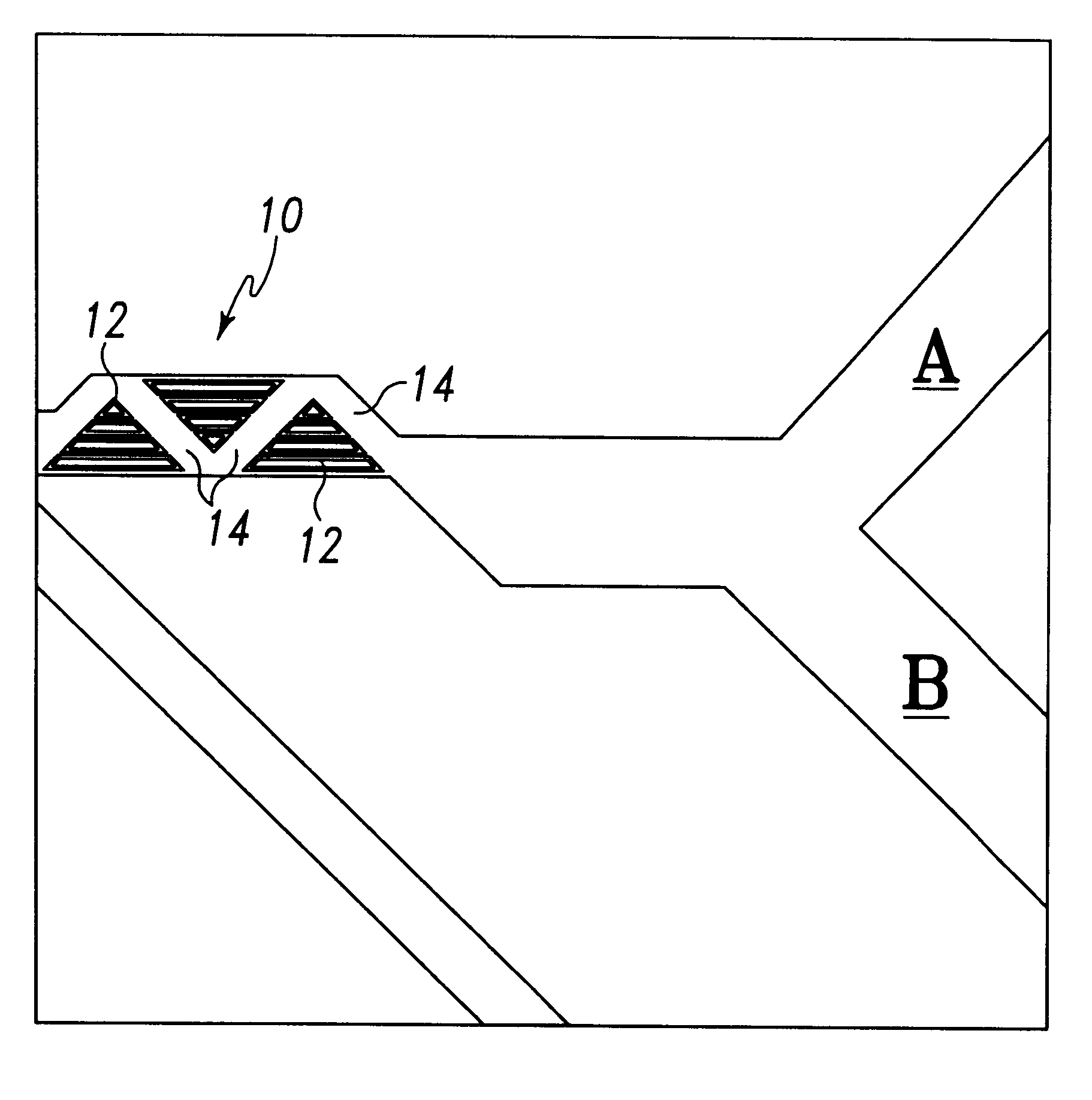
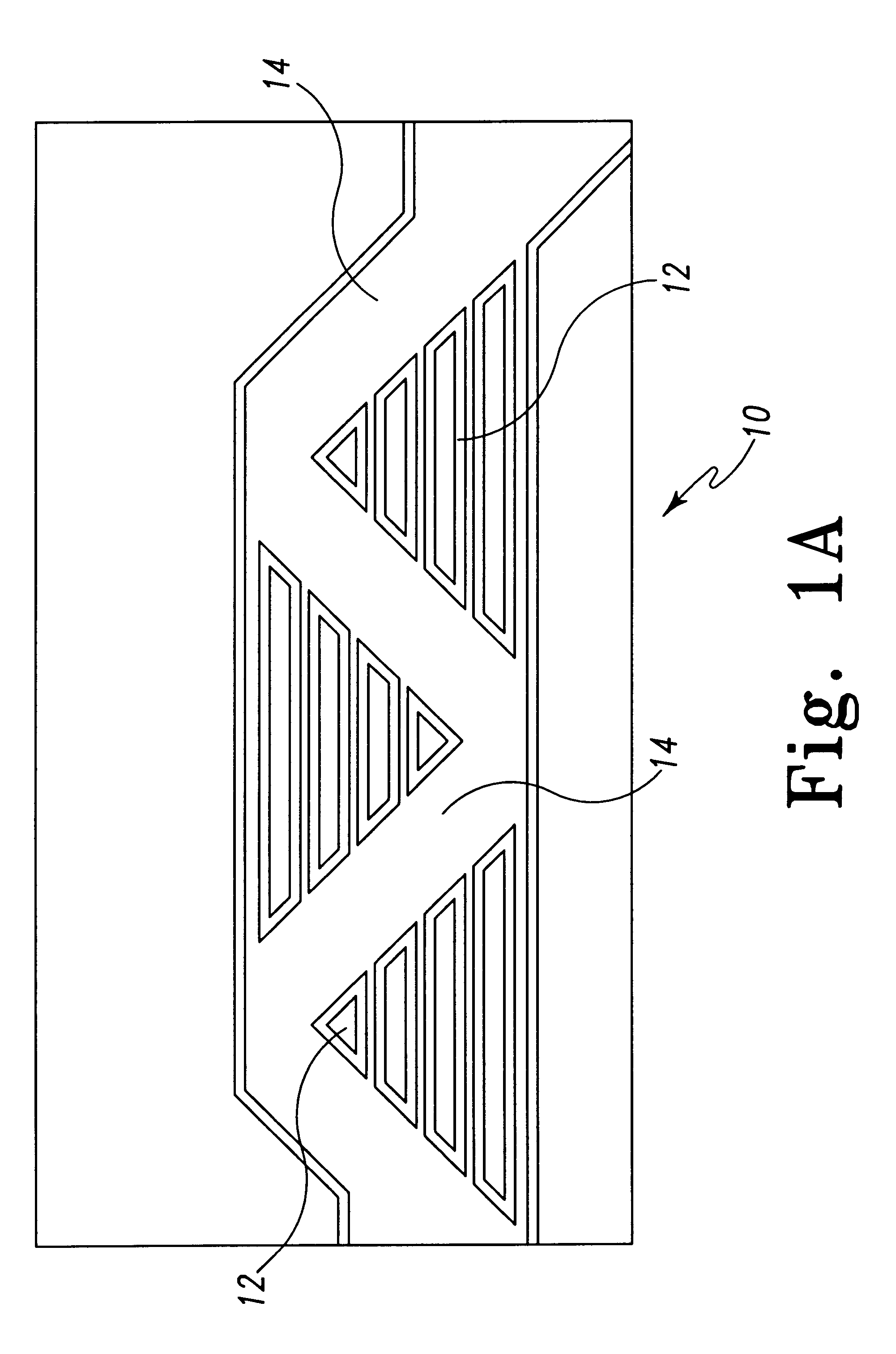
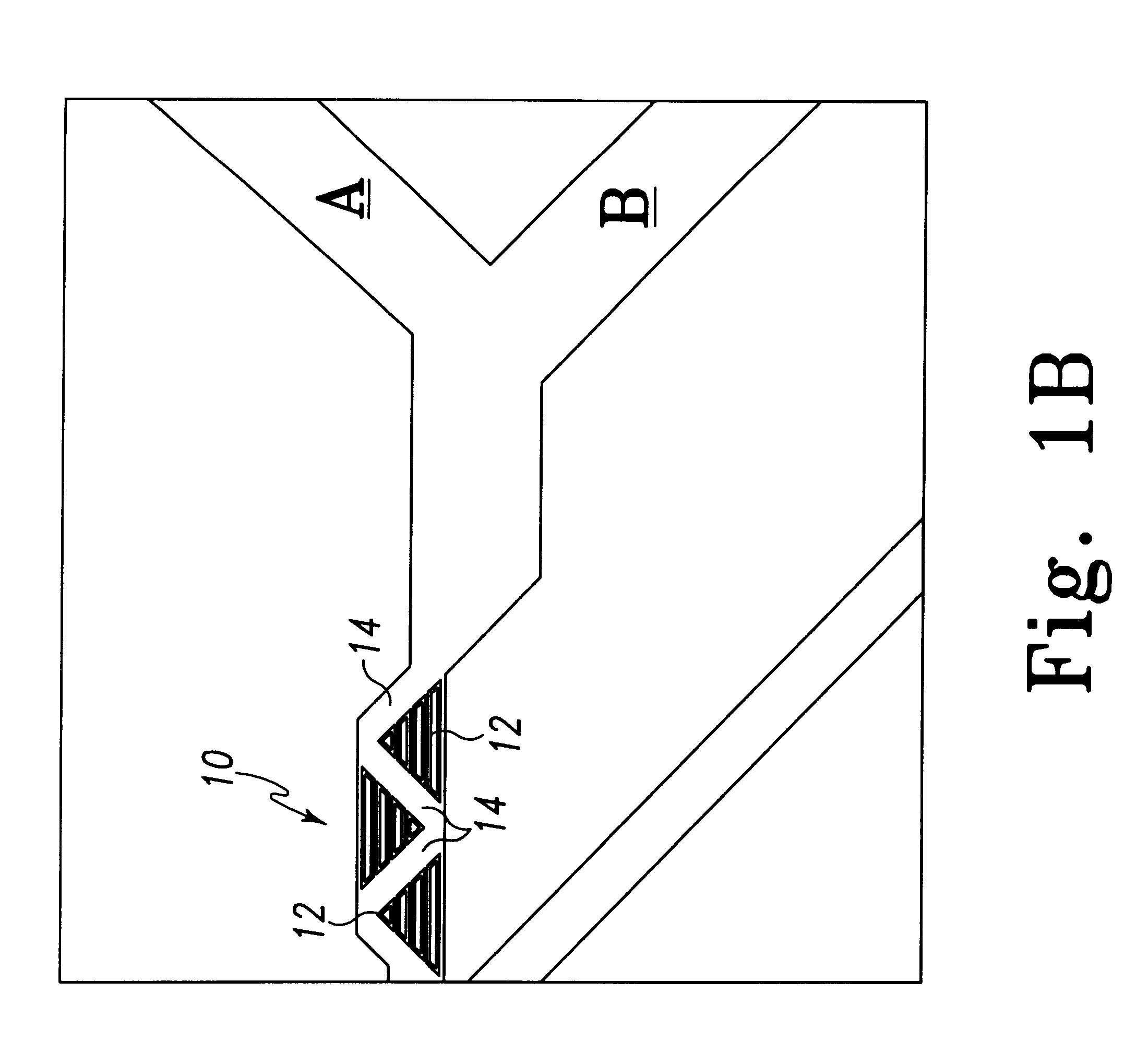
Transport channels in microfluidic systems are most frequently formed by wet etching roughly 10-20 .mu.m deep channels of 100 .mu.m width into an inorganic substrate and enclosing them with a transparent plate. Polysilicon, glass, and quartz are the materials of choice in microfabricated, microfluidic systems because of their wide use in electronics and micro-electromechanical systems and because of the advancement of the tech...


PUM


Abstract

The present invention relates to an in situ micromachined mixer for microfluidic analytical systems. In a preferred embodiment, a 100 pL mixer for liquids transported by electroosmotic flow (EOF) is described. Mixing was achieved in multiple intersecting channels with a bimodal width distribution and varying lengths. Five .mu.m width channels ran parallel to the direction of flow whereas larger 27 .mu.m width channels ran back and forth through the network at a 45.degree. angle. All channels were approximately 10 .mu.m deep. It was observed that little mixing of confluent streams occurred in the 100 .mu.m wide mixer inlet channel where mixing would be achieved almost exclusively by diffusion. In contrast, mixing was complete after passage through the channel network in the .apprxeq.200 .mu.m length mixer. Solvent composition was altered by varying the voltage on solvent reservoirs. The high efficiency attained in this mixer was attributed to the presence of a 2 pL vortex in the center of the mixer. Video tracking of fluorescent particles with a fluorescence microscope allowed the position and volume of this vortex to be determined.

Description

TECHNICAL FIELD OF THE INVENTIONThe present invention generally relates to the mixing of confluent liquid streams in microfluidic systems and, more particularly, to an in situ micromachined mixer for microfluidic analytical systems.BACKGROUND OF THE INVENTIONMerging two or more liquids to form a solution generally requires some combination of convective and diffusive transport. This is a critical element of many analytical methods. Although blending by convective transport alone can be achieved very quickly, it only provides a macroscopic level of mixing. Efficient mixing within convectively generated microenvironments requires diffusion. Diffusive mixing is most effective when the transport distance is a few microns or less.Convective transport is a physical process requiring energy. Generally, this energy is provided in the form of mechanical agitation, as in the case of mechanical stirrers or vortex mixers. This direct addition of energy at the point of mixing is perhaps the reas...

Claims


Application Information

Patent Timeline
Patent Type & Authority Patents(United States)
IPC IPC(8): B01L3/00B01F13/00B01F5/06B81B1/00
CPCB01F5/0645B01F13/0059B01F13/0093B01L3/502746B01F2215/0037B01L3/5027B01L2300/0867B01L2400/0421Y10S366/03G01N2030/347B01F25/43231B01F33/3039B01F33/30B01F2101/23
Inventor REGNIER, FREDHE, BING
Owner PURDUE RES FOUND INC
Why Eureka
Try Eureka