Adjustable rear-view mirror for a vehicle

a rearview mirror and adjustable technology, applied in the field of adjustable rearview mirrors, can solve the problems of large space requirement, large number of additional components, and large weight of the device, and achieve the effect of reducing and increasing the weight of the devi

Inactive Publication Date: 2001-01-16
MAGNA AUTECA ZWEIGNIEDERLASSUNG DER MAGNA HLDG
View PDF26 Cites 36 Cited by
  • Summary
  • Abstract
  • Description
  • Claims
  • Application Information

AI Technical Summary

Benefits of technology

In order to permit a swiveling of the mirror in all directions in simple fashion, it is moreover provided in accordance with an additional preferred embodiment that two drive motors designed with pinions, with a reducing gear interposed if necessary, are mounted in the interior of the inner element, whose pinions meshing with the inner surface of the outer element together enclose an essentially right angle and that the gear-tooth systems on the inner surface of the outer element meshing with the pinions each extend over an angular range corresponding to a swivel angle associated with the other pinion of the outer relative to the inner element. Through provision of reducing gears, simple and small motors can be used, whereby mutual arrangement of the drive pinions at a right angle to one another also permits the mirror to achieve all spatial positions. Since with adjustment of one pinion, the other pinion must follow the gear-tooth system on the inner surface of the outer dish-shaped element, it is further provided in accordance with the invention that the gear-tooth systems each extend in an arc over a corresponding angular region on the surface of the outer element of the rearview mirror in accordance with the invention.
For an additional improvement of the mutual support and positioning of the dish-shaped elements of the rearview mirror in accordance with the invention, it is further preferably suggested that the two dish-shaped elements in the region of the center point of the spherical surfaces be additionally supported against one another via a spherical bearing or a universal joint and that the inner element be designed with one edge running obliquely outward starting from the spherical bearing in the center, whose angle of inclination relative to a diameter of the spherical surface corresponds to at least the maximum swivel angle of the dish-shaped elements relative to one another. In addition to the areal support of the dish-shaped elements with one another via the spherical areas of contact, such a spherical bearing or a universal joint defines an exact swivel point of the elements movable relative to one another and thus increases the mutual bearing stability. In order to avoid a collision between the two dish-shaped elements during swiveling of the same, it is further provided in accordance with the invention that the inner element be designed with one edge running obliquely outward starting from the spherical bearing in the center, whose angle of inclination relative to a diameter of the spherical surface corresponds to at least the maximum swivel angle of the dish-shaped elements relative to one another.
For a further increase in the internal stability of the overall design of the rearview mirror in accordance with the invention and for avoidance of mutual displacements between the individual elements, it is further preferably provided that a connection with the outer dish on the side away from the bearing be provided starting from the spherical bearing or the universal joint in a manner known per se.
For additional optimization of weight, it is further preferably suggested that the axes of the drive pinion(s) in the region of the outside edge of the rearview mirror be (are) arranged in the interior of the inner element, which results in the largest possible distance from the swivel point so that the drive can be driven with a particularly low expenditure of force.
For a particularly simple arrangement of the rearview mirror in accordance with the invention, it is provided in accordance with a preferred embodiment that the inner dish-shaped element is attachable to the vehicle in a manner known per se and that the outer dish-shaped element projects beyond the inner element at least on the side facing away from the attachment of the inner element to the vehicle and forms or exhibits a mount for a mirror. Thus the inner dish-shaped element can be designed simply with an appropriate extension or a mount for attachment to the vehicle, whereby appropriate design changes and adaptations are also possible without impairing the swivel capability of the elements of the rearview mirror. Furthermore, the outer dish-shaped element, when appropriately shaped, can also be designed as a mount for a mirror or can be provided with such a mount.

Problems solved by technology

Provided for the adjustment or as a drive in these known designs are rack-and-pinion gears, costly in terms of design, which make necessary a multitude of additional components and a large space requirement.
Disadvantageous in these known design forms is in general that an essentially point support is provided to the elements capable of swiveling relative to one another, which is relatively unstable especially with respect to shocks and vibrations.
Additionally disadvantageous is that essentially the entire swiveling mechanism, and thus the largest part of the weight of the device is concentrated in a very small space in the region of the swivel point.

Method used


Image

  • Adjustable rear-view mirror for a vehicle
  • Adjustable rear-view mirror for a vehicle
  • Adjustable rear-view mirror for a vehicle

Examples


Embodiment Construction

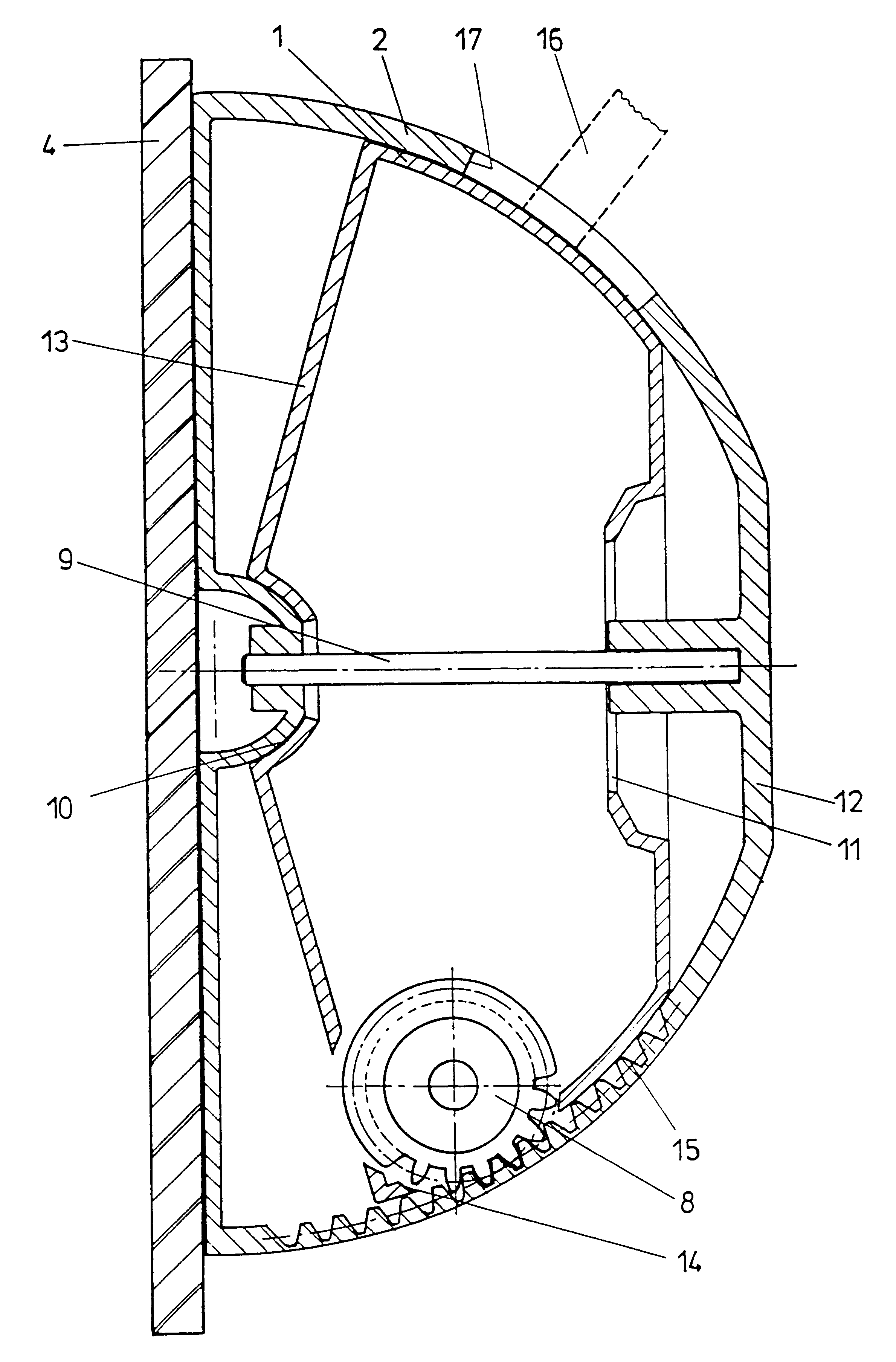
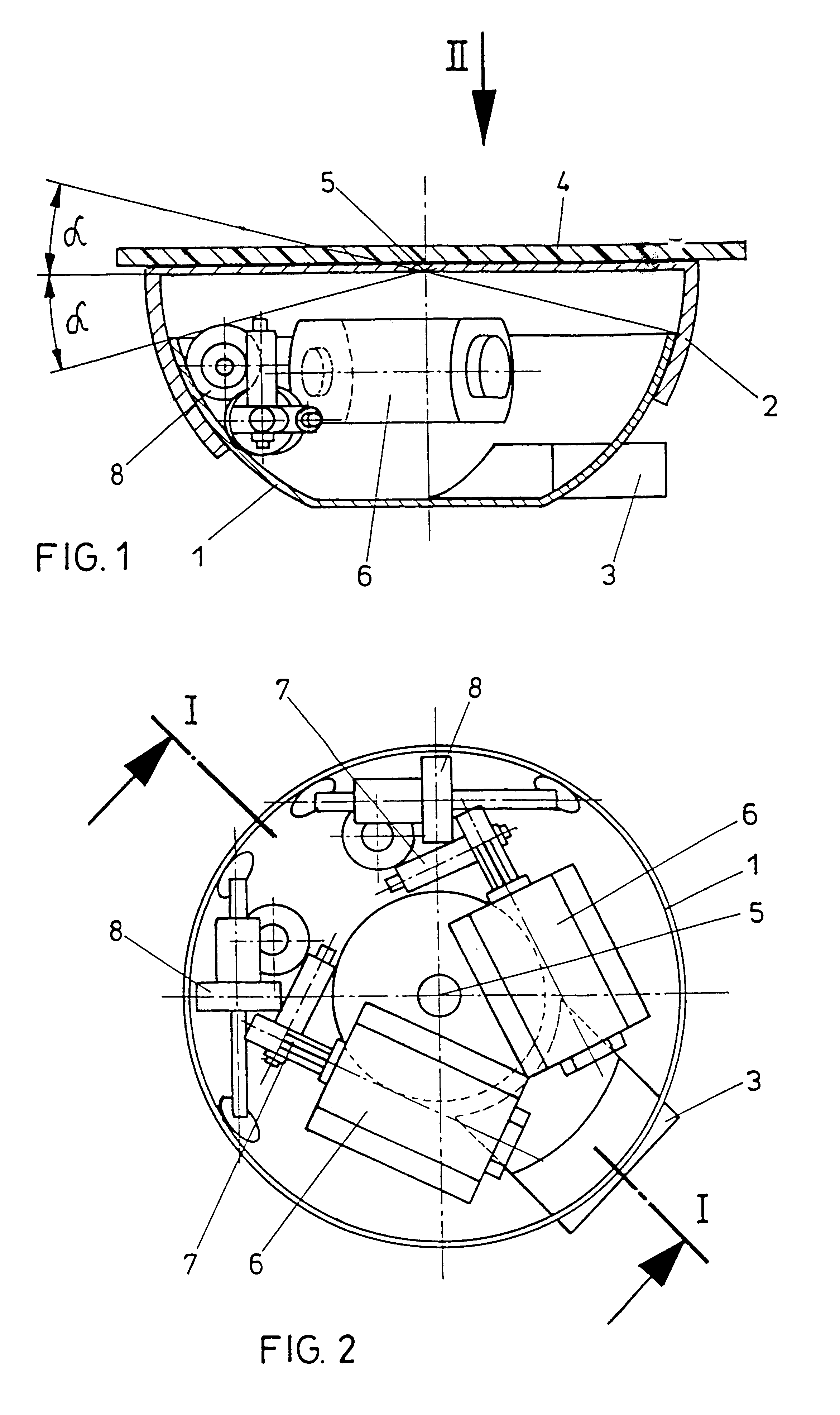
In the illustration in accordance with FIGS. 1 and 2, an inner dish-shaped element of a rearview mirror is designated 1 and is partially overlapped by an outer dish-shaped element 2, as can be clearly seen from FIG. 1. The outer dish-shaped element 2 projects here beyond the inner element 1, which is designed with a mount schematically designated 3 for attachment of the entire mirror to a vehicle that is not illustrated in detail, and serves the attachment of a mirror schematically designated 4 on this side facing away from the mount 3.

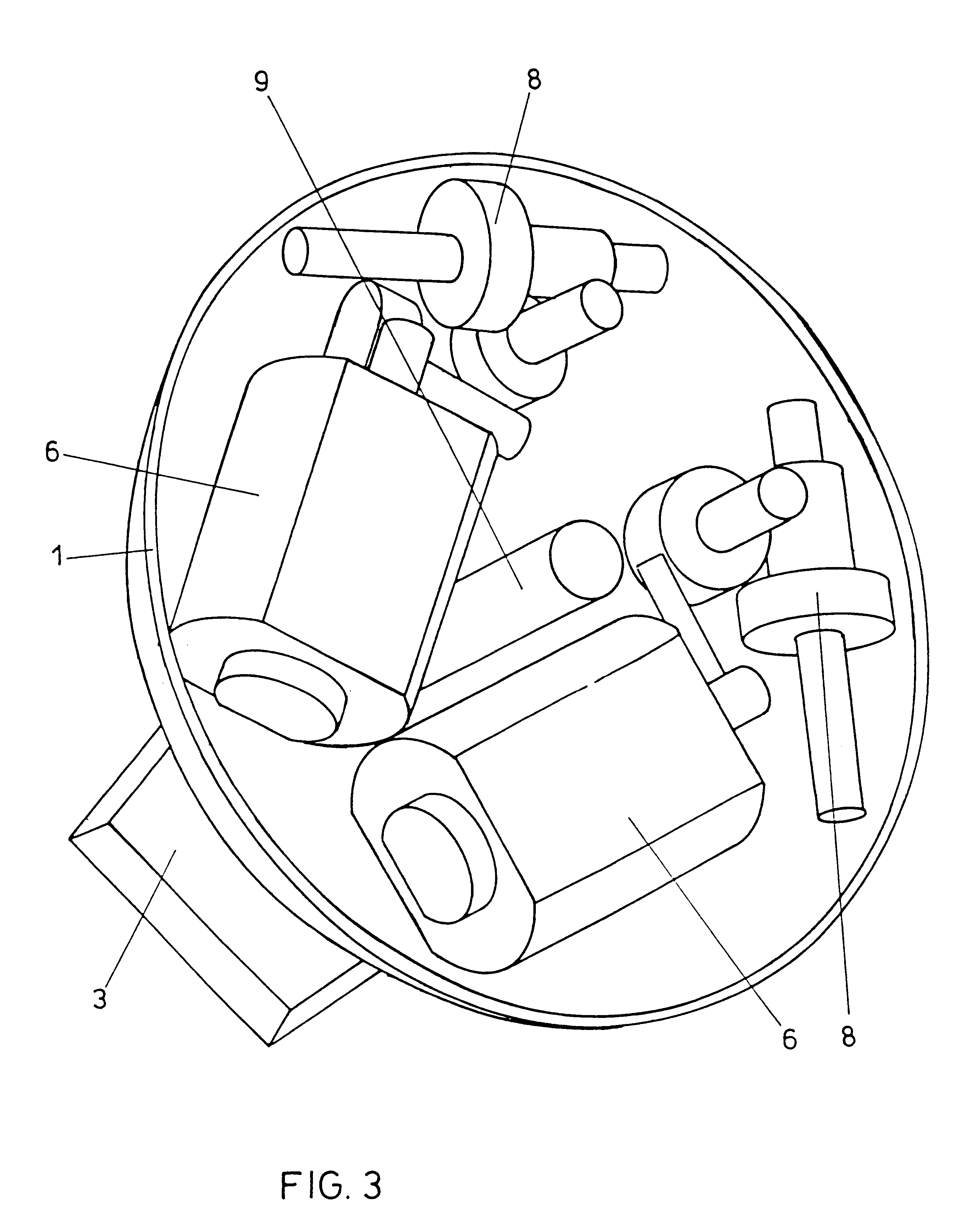
As can be seen especially from FIG. 1, the dish-shaped elements 1 and 2 are each designed with areas of contact forming segments of a spherical surface, so that the overall result is a large supporting area between elements 1 and 2 at a great distance from the swivel center point designated with 5. For swiveling of the outer element 2 that bears the mirror 4, relative to the inner element 1 that is attached to the vehicle, two drive motors 6 are provi...


PUM


Abstract

In an adjustable rearview mirror, especially an outside mirror, for a motor vehicle, whereby a first element (1) is affixable to the vehicle and a second element (2), rotatably attached to the first element (1), has or forms a mount for a mirror (4), whereby the two elements (1, 2) are designed as dish-shaped elements (1, 2) that nest with one another at least partially and are guided or bear against one another via outside and inside areas of contact forming a segment of a spherical surface and whereby a drive (6) is provided between the first and the second element (1, 2) is proposed, characterized in that the outer element (2) is designed on part of its inner surface with a gear-tooth system extending along a circular section of the inner surface of the outer element (2), with which a pinion (8) of a drive (6) mounted in the inside of the inner element (1) meshes for adjustment of the outer element (2) relative to the inner element (1), by which means can be achieved with a simple construction a design that is largely insensitive to vibrations.

Description

1. Field of the InventionThe present invention concerns an adjustable rearview mirror, especially an outside mirror, for a motor vehicle, whereby a first element is affixable to the vehicle and a second element, rotatably attached to the first element, exhibits or forms a mount for a mirror, whereby the two elements are designed as dish-shaped elements that nest with one another at least partially and are guided or bear against one another via outside and inside areas of contact forming a segment of a spherical surface and whereby a drive is provided between the first and the second element.2. Discussion of Background InformationFrom AT-B 256 645 and DE-B 12 41 295, a motor vehicle outside rearview mirror combined with an electric lamp has become known, whereby two dish-shaped elements that nest partially with one another are provided and a lamp is to be integrated in the mirror, whereby no drive is provided between the individual dish-shaped elements, however.Adjustable rearview mi...

Claims


Application Information

Patent Timeline
Patent Type & Authority Patents(United States)
IPC IPC(8): B60R1/062B60R1/072B60R1/06
CPCB60R1/072
Inventor SCHILLEGGER, PETERFINK, GERALDPACHER, WOLFGANG
Owner MAGNA AUTECA ZWEIGNIEDERLASSUNG DER MAGNA HLDG
Why Eureka
Try Eureka