This helps you quickly interpret patents by identifying the three key elements:
Problems solved by technology
Method used
Benefits of technology
Benefits of technology
An object of the present invention is to provide a device making it possible to reduce and / or to cancel out the effect of temperature on a (de)multiplexing device without it being necessary to take any action external to the device, and regardless of the material used (SiO.sub.2, InP, polymer, Al.sub.2 O.sub.3, LiNbO.sub.3, etc.)
An additional object of the present invention is to provide a device organized either to reduce the effect of temperature, or to increase it to offer means of controlling the signal, by means of temperature on the desired channel. In this way, the invention makes it possible to offer greater tolerance as regards the geometrical configuration of the device.
By cancelling out the effect of temperature, it is no longer necessary to provide an external regulation device.
Problems solved by technology
Unfortunately, they are not entirely satisfactory.
The main drawback with such known devices is their high degree of temperature dependency which is intrinsic to the material used.
Unfortunately, that material offers only limited possibilities as regards monolithic integration (integration on the same material) of devices such as lasers, optical amplifiers, or detectors.
Unfortunately, the refractive index of InP varies considerably with temperature (giving rise to an offset of about 1 nm per 10.degree. C.).
That heavy dependency requires the temperature to be controlled by means external to the device, e.g. in the form a Peltier-effect element, which increases the cost of implementing the device.
Image
Click on the blue label to locate the original text in one second.
Reading with bidirectional positioning of images and text.
Examples
first embodiment
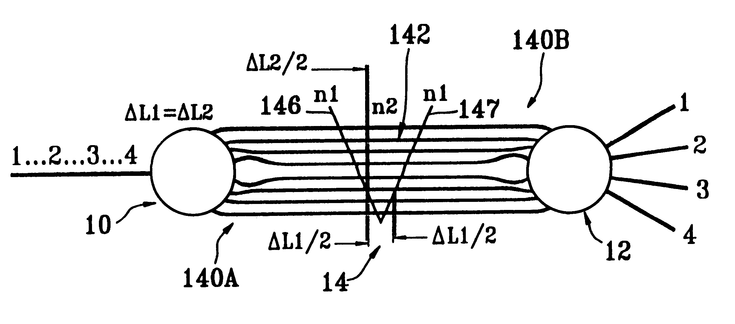
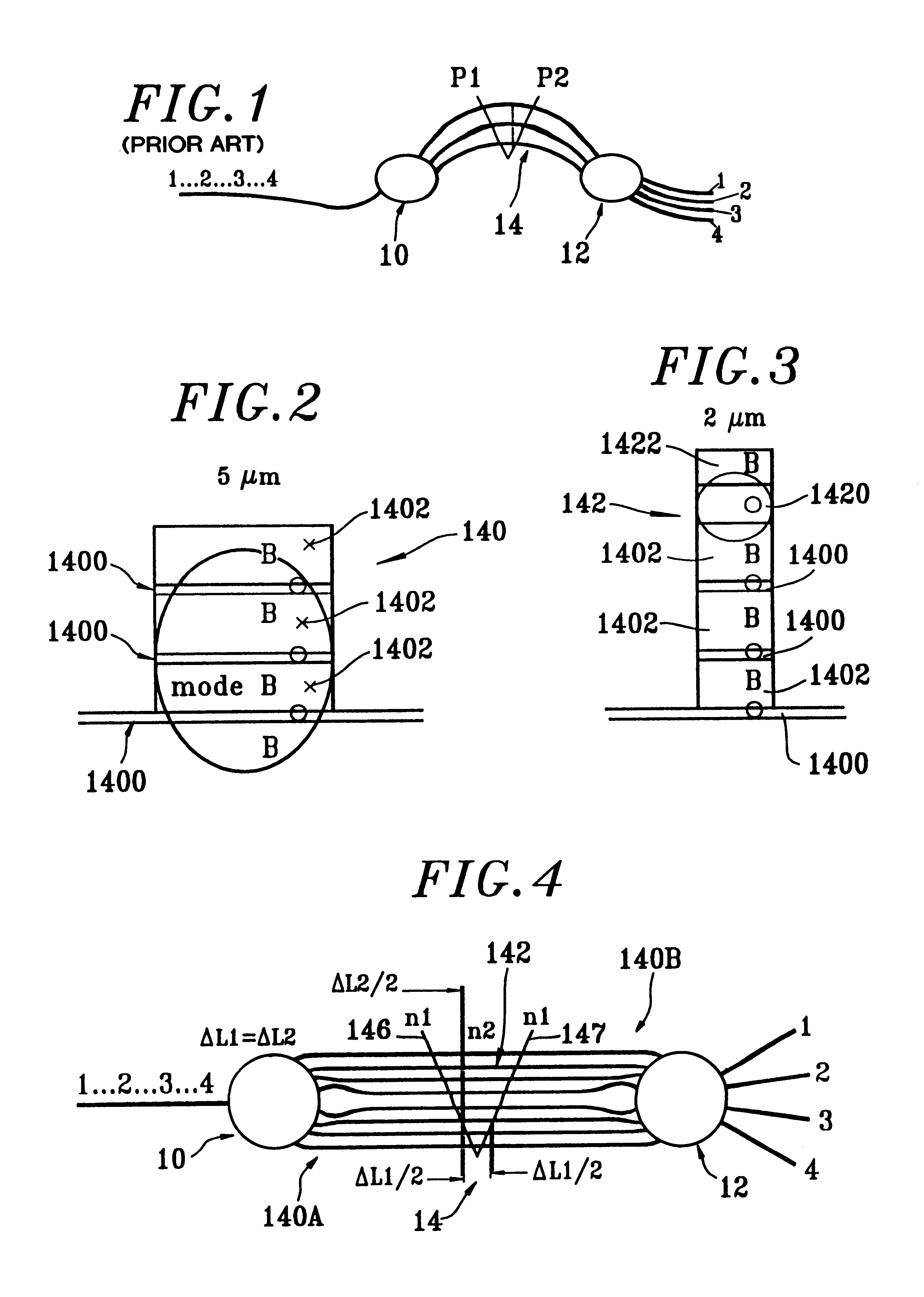
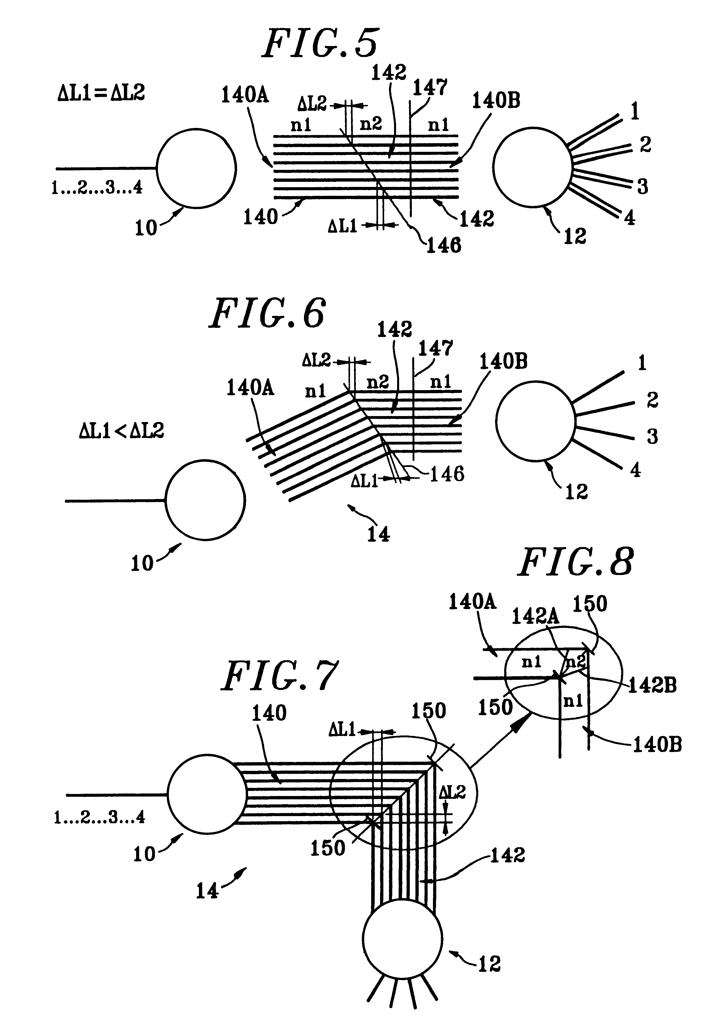
In the first embodiment, the refractive indices of the materials of both spans 140, 142 of each waveguide 14 vary with temperature in the same direction, but the two spans 140, 142 have respective lengths that vary in opposite directions from one waveguide to another.
FIGS. 4, 5, and 6 show three variants of such a device.
The equation giving the center wavelength .lambda. as a function of the difference between the path lengths of two consecutive guides in such a structure is as follows:
where .DELTA.L1>0 is the difference between the path lengths of two consecutive waveguides 14 for the material of refractive index n1 forming respective first spans 140; and
where .DELTA.L2>0 is the difference between the path lengths of two consecutive waveguides 14 for the material of refractive index n2 forming respective second spans 142.
The demultiplexer is designed such that .DELTA.L2=K.DELTA.L1
where k=(dn1 / dT) / (dn2 / dT)=K1 / K2>0, i.e. the refractive indices of t...
second embodiment
In the second embodiment, the refractive indices vary with temperature in opposite directions for the materials of the two spans 140, 142 of each waveguide 14, and the respective spans 140, 142 have lengths that vary in the same direction from one waveguide to another.
FIGS. 7, 8, and 9 show three variants of such a device.
The equation giving the center wavelength 1 as a function of the difference between the path lengths of two consecutive waveguides in such a structure is as follows:
where .DELTA.L1>0 is the difference between the path lengths of two consecutive waveguides 14 for the material of refractive index n1 forming respective first spans 140; and
where .DELTA.L2>0 is the difference between the path lengths of two consecutive waveguides 14 for the material of refractive index n2 forming respective second spans 142.
The demultiplexer is designed such that .DELTA.L2=K.DELTA.L1
where k=-(dn1 / dT) / (dn2 / dT)>0, i.e. the refractive indices of the mat...
PUM
Abstract
The present invention concerns a device forming an optical multiplexer and / or demultiplexer of the type including two plane optical surfaces separated by an array of waveguides having controlled differences in length, wherein each waveguide comprises at least two spans placed in series and having respective lengths and refractive indices that are suitable for controlling the influence of temperature variations on the device.
Description
The present invention relates to the technical field of light guides.The present invention proposes an optical multiplexer and / or demultiplexerusable in the fields of telecommunications and of remote sensors.The device of the invention may constitute an optical receiver for a direct-detect reception circuit, e.g. for optical-link systems. Such a device may be advantageous for separating signals of different wavelengths arriving over a common fiber so as to distribute them to different users, each receiving a specific wavelength.The device of the invention may also be coupled (in hybrid or integrated manner) with transmission lasers or optical amplifiers.The device of the invention is particularly advantageous in switching, cross-connection, and local loop functions. It may be also used in optical interconnections between, for example, highly integrated high-speed electronic chips, or between computers, or else within a computer.Various optical multiplexer and / or demultiplexer struc...
Claims
Application Information
Patent Timeline
Application Date:The date an application was filed.
Publication Date:The date a patent or application was officially published.
First Publication Date:The earliest publication date of a patent with the same application number.
Issue Date:Publication date of the patent grant document.
PCT Entry Date:The Entry date of PCT National Phase.
Estimated Expiry Date:The statutory expiry date of a patent right according to the Patent Law, and it is the longest term of protection that the patent right can achieve without the termination of the patent right due to other reasons(Term extension factor has been taken into account ).
Invalid Date:Actual expiry date is based on effective date or publication date of legal transaction data of invalid patent.

