Rotary shaft tool

a technology of rotary shaft and tool, which is applied in the direction of boring/drilling equipment, reaming tools, turning equipment, etc., can solve the problems of unusable workpieces, insufficient chip removal for trouble-free operation, and rotary shaft tools, so as to reduce pressure, and improve the effect of chip carrying

Inactive Publication Date: 2001-02-06
BECK GMBH & CO AUGUST
View PDF8 Cites 17 Cited by
  • Summary
  • Abstract
  • Description
  • Claims
  • Application Information

AI Technical Summary

Benefits of technology

The construction of the chip space according to the invention has the advantage that due to the tapering of the chip space at the end of the cutter head a suction action arises in the adjoining enlarged chip space because of the reduced pressure. As a result, the chips do not reach the floor of the blind hole, but are flushed out of the bore in the direction toward a tool holding fixture of the rotary tool. In addition, a venturi effect occurs during chip transport in the region of the tapered section, which is enlarged toward the following chip space section. This venturi effect, in connection with the supply of coolant / lubricant in a conduit of the shaft tool, insures carrying away the chips out of the blind hole bore.
According to an advantageous embodiment of the invention, the narrowest cross section of the tapering chip space is located in the region of the main cutting edge. Thus, a venturi effect occurs, which serves to improve carrying away the chips, in the region where the greatest part of the chips are obtained and are to be carried away, so that the effect can be substantially increased. The surface quality of the blind hole bore can thereby be improved.
According to an advantageous embodiment of the invention, the tapering section of the chip space merges into a further chip space section that preferably has a constant cross section. A simple machining of the chip space is thereby made possible. This advantageously results when the course of a side face of the inner chip space of the tapering chip space section corresponds to a diameter of a milling cutter with which the chip space is produced. Consequently a linear motion of the machining tool can be sufficient to produce the tapering of the chip space. Furthermore a path-controlled guiding of the milling cutter can be provided for the production of the chip space, in order to produce a corresponding geometry for the tapering chip space.

Problems solved by technology

Such rotary shaft tools have the disadvantage that sufficient chip removal is not provided for a trouble-free operation, particularly for machining blind hole bores.
The chips that are not carried away from the blind hole bore cause an impairment of the bore surface being machined, so that workpieces become unusable.

Method used


Image

  • Rotary shaft tool
  • Rotary shaft tool
  • Rotary shaft tool

Examples


Embodiment Construction

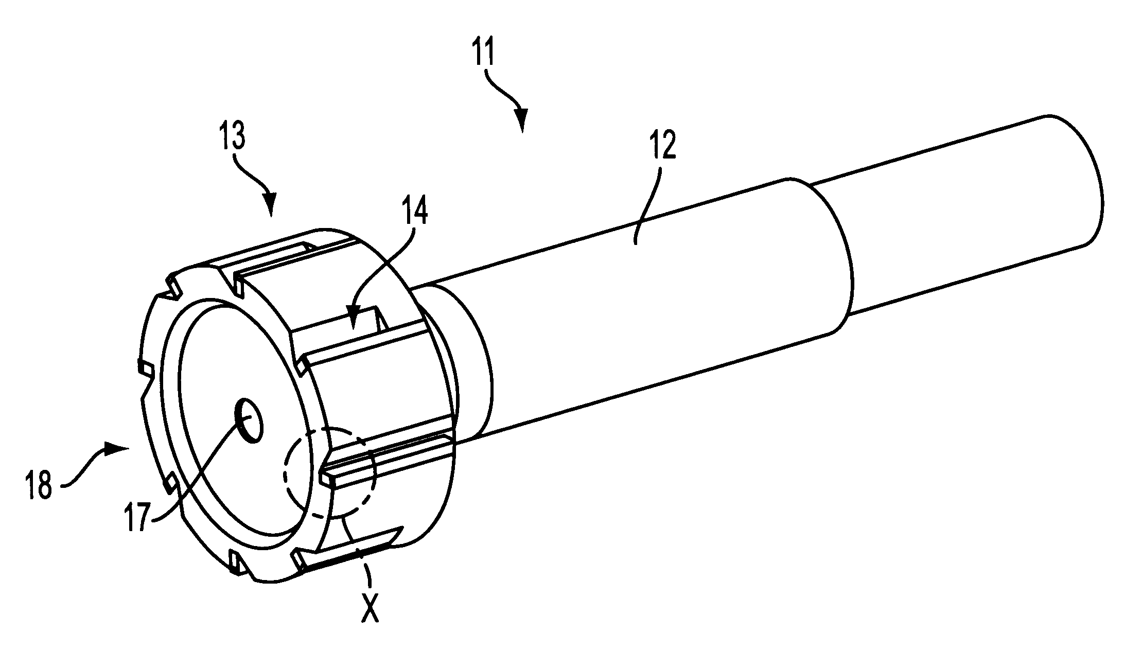
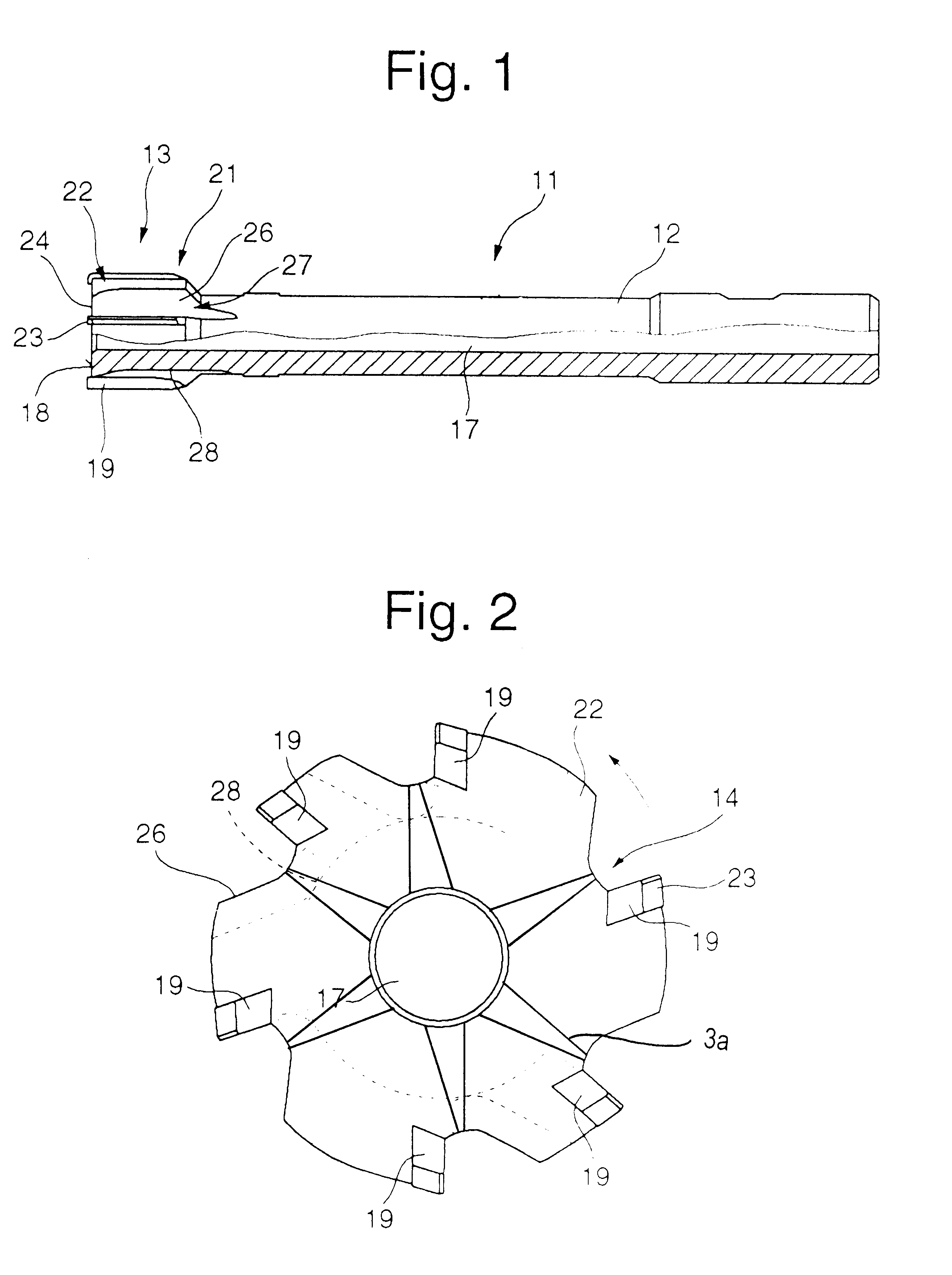
A rotary shaft tool 11 is shown in FIG. 1 and FIG. 4A, and has a cylindrical shaft 12 and also a cutter head 13. The cutter head 13 can be produced as a molded head of cutting tool material and inserted into the shaft of less expensive material. The rotary cutting tool also can be produced integrally from a cutting tool material.

The cutter head 13 has chip spaces 14 on which an outlet region 16 is provided that faces toward the shaft 12. A longitudinal conduit 17 that preferably runs centrally in the shaft tool 11 is provided in the shaft 12 and cutter head 13, in order to conduct coolant or lubricant liquid or a cooling emulsion into the bore.

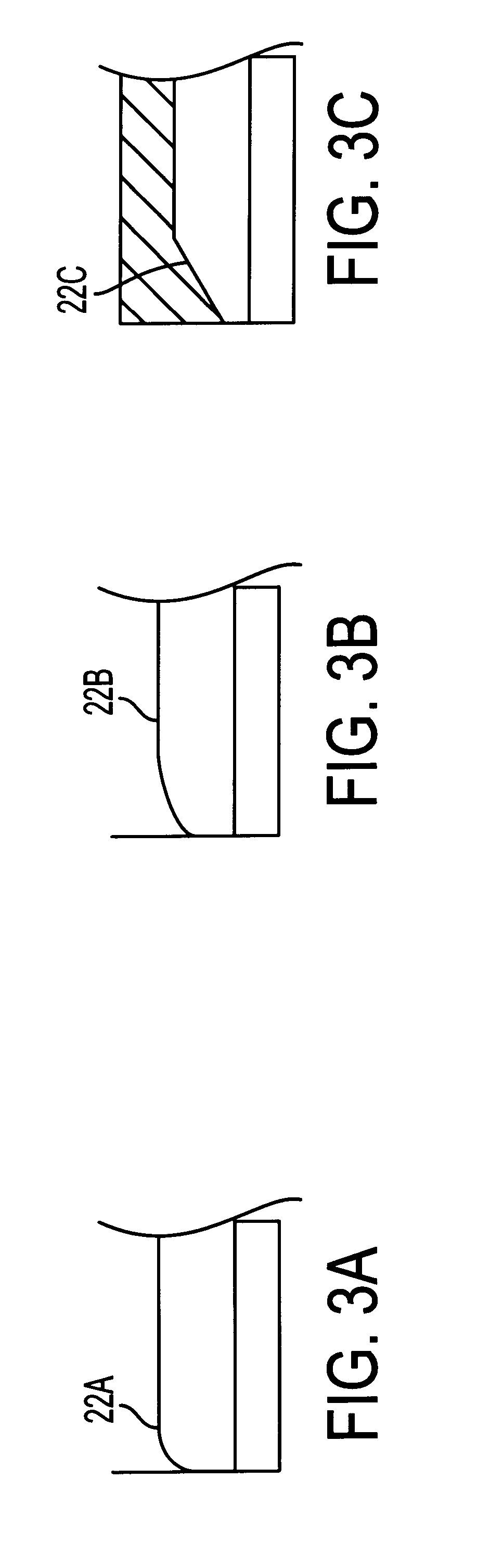
FIG. 2 and FIG. 4B show a plan view of the end 18 of the cutter head 13. This cutter head has, for example, six cutting edges 19, with a preceding chip space 14 respectively associated with each. FIG. 4A and 4B show the cutter head has, for example, eight cutting edges 19. FIG. 4A identifies the portions "X" shown in enlarged detail in FIG. 3A...


PUM

PropertyMeasurementUnit
pressuresaaaaaaaaaa
pressureaaaaaaaaaa
surface qualityaaaaaaaaaa

Abstract

A rotary shaft tool for machining bores, particularly blind hold bores, has a shaft with at least one longitudinal conduit for coolant/lubricant, with a cutter head that has at least one cutting edge and a chip space. A chip space section is provided that tapers toward the end of the cutter head.

Description

1. Field of the InventionThe invention relates to a rotary shaft tool for machining bores, and more particularly a rotary shaft tool for machining blind hole bores.2. Discussion of Related ArtFor machining bores, particularly for fine machining or high speed machining, rotary shaft tools are known that are constructed as single-blade or multi-blade reamers. The reamers have a shaft in which at least one longitudinal conduit for coolant / lubricant extends. The shaft is connected to a cutter head that has at least one chip space or chip groove. This chip space has a constant cross section, at least in the region of the main cutting edge and minor cutting edge. This continuous cross section of the chip space can merge into a chip discharge region, which is then usually enlarged in comparison with the continuous cross section of the chip space.Such rotary shaft tools have the disadvantage that sufficient chip removal is not provided for a trouble-free operation, particularly for machinin...

Claims


Application Information

Patent Timeline
Patent Type & Authority Patents(United States)
IPC IPC(8): B23D77/00B23B51/04
CPCB23B51/0486B23D77/006Y10T408/9095Y10T408/455
Inventor RITTER, OTTO
Owner BECK GMBH & CO AUGUST
Why Eureka
Try Eureka