Fluid distributor assembly for a multi-bed, downflow catalytic reactor

Inactive Publication Date: 2001-02-06
CHEVROU USA INC
View PDF12 Cites 61 Cited by
  • Summary
  • Abstract
  • Description
  • Claims
  • Application Information

AI Technical Summary

Benefits of technology

A plurality of semi-spiral-shaped baffles are optionally fixably disposed in the third mixing zone, the semi-spiral-shaped baffles having an elongated shape. Each semi-spiral-shaped baffle optionally has one lateral edge fixed to an inner surface of the cap, or alternatively an opposite lateral edge fixed to an outer surface of the first cylindrical weir, or utilizes any other conventional attachment method, and having one longitudinal end disposed proximal to a bottom portion of the first cylindrical weir but above a top portion of the slots in the cap; and having an opposite longitudinal end disposed proximal to a top portion of the first cylindrical weir, configured for causing the liquid and gas in the third mixing zone to move laterally and for causing further mixing of the liquid and gas.
A substantially doughnut-shaped screen member, typically a thin or flattened shape as to thickness but maintaining roundness along the inner and outer circumferences, disposed over a top por

Problems solved by technology

In exothermic reactions, large amounts of heat may be generated in the catalyst beds.
Unless this is mitigated, the reactor operation would be inefficient and hot spots may develop that could potentially shorten catalyst life and force premature reactor shutdown and therefore plant shu

Method used


Image

  • Fluid distributor assembly for a multi-bed, downflow catalytic reactor
  • Fluid distributor assembly for a multi-bed, downflow catalytic reactor
  • Fluid distributor assembly for a multi-bed, downflow catalytic reactor

Examples


Embodiment Construction

A. Elements

The elements for the assembly and corresponding reference numbers as used in the figures are listed in Table 1 below. In the section following this one, each element and how it relates to the other elements is described in detail with reference to the figures.

B. Organization Of Elements Of The Distributor Assembly For A Catalytic Reactor

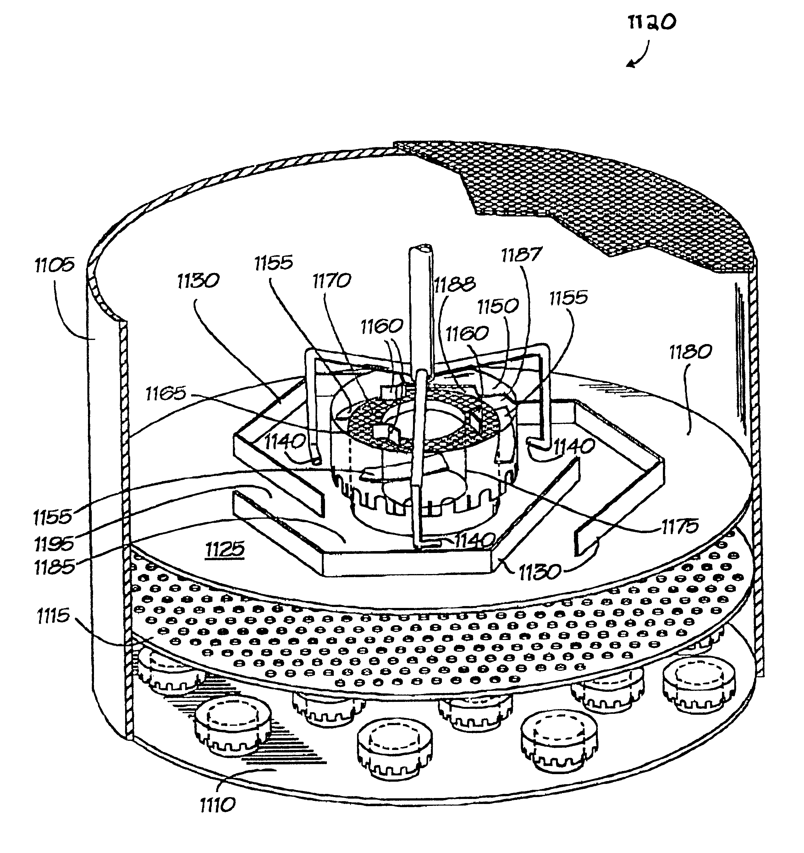
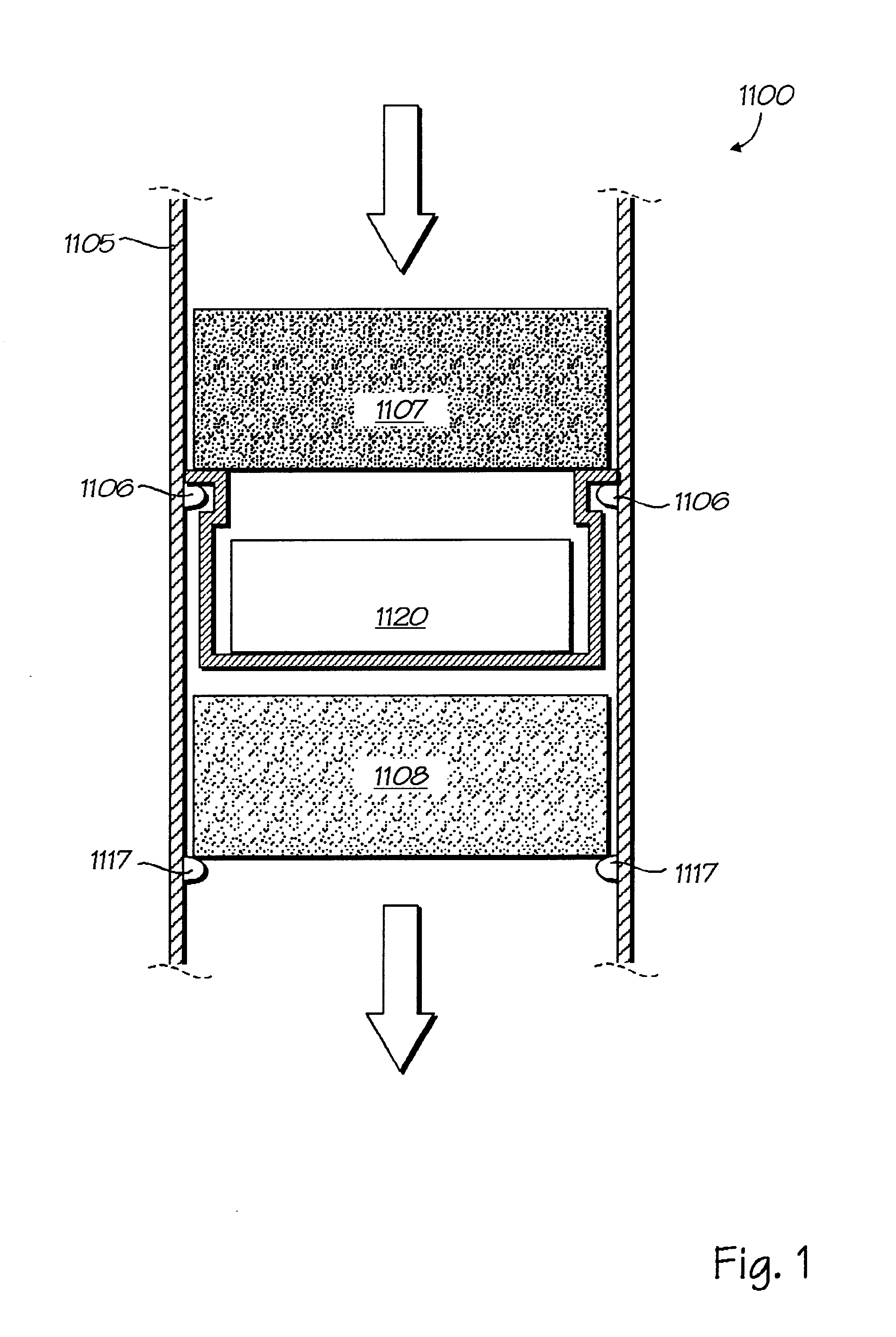
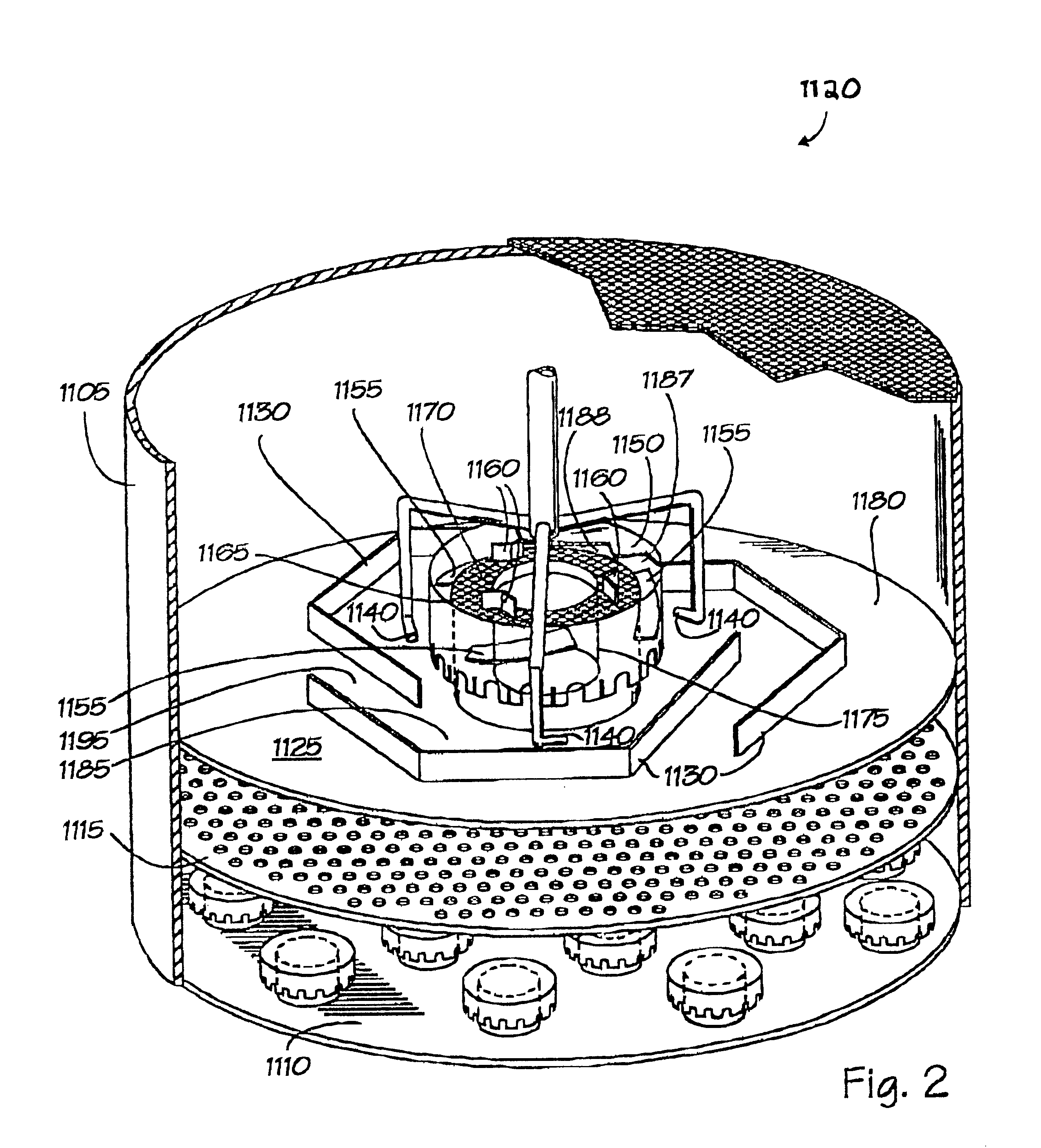
FIG. 1 depicts an overview schematic cut-away view of a multi-bed, down-flow reactor 1100 with the distributor assembly of the invention included therein. It has a cylindrical reactor wall 1105 and a first mounting means 1106 fixably attached to the cylindrical reactor wall 1105. Reactor 1100 is configured for supporting catalyst beds 1107-1108 containing packed particulate catalytic material (not shown) in vertically superimposed relation to each other to permit liquid and gas to flow from a higher catalyst bed 1107 to a lower catalyst bed 1108. A typical first mounting means 1106 optionally includes a strut member fixably attached to the...


PUM

PropertyMeasurementUnit
Fractionaaaaaaaaaa
Fractionaaaaaaaaaa
Fractionaaaaaaaaaa

Abstract

A distributor assembly for a multi-bed, downflow catalytic reactor is disclosed. The distributor assembly is configured for disposal and fixable attachment between the inner surfaces of the walls of a multi-bed downflow cylindrical reactor wall and for disposal between vertically stacked catalyst beds within the reactor. The assembly includes:(a) a collection plate configured for substantially horizontal disposal between the walls of a cylindrical reactor;(b) a plurality of generally arc-shaped elongated baffles disposed in a staggered, substantially symmetrical pattern about the collection plate;(c) a first mixing zone configured to be bounded on the bottom by the collection plate, on one side by a wall of a cylindrical reactor, and on the opposite side by the outer surface of the elongated baffles;(d) a cylindrical weir fixably attached to the collection plate about the outlet;(e) a second mixing zone bounded on the bottom by the collection plate, on one side by the outer surface of the cap and the first cylindrical weir, and on the opposite side by the inner surface of the elongated baffles;(f) a cap disposed over and about the first cylindrical weir, thereby forming a third mixing zone, plurality of semi-spiral-shaped baffles disposed in the third mixing zone, the semi-spiral-shape;(g) baffles having an elongated shape, having one lateral edge fixed to an inner surface of the cap or an opposite lateral edge fixed to an outer surface of the first cylindrical weir;(h) a substantially doughnut-shaped screen member disposed over a top portion of the cylindrical weir;(i) a plurality of fourth-mixing-zone baffles fixably attached to a top surface of the doughnut-shaped screen member; and(j) a plurality of quench gas ports disposed in the second mixing zone.

Description

I. FIELD OF THE INVENTIONThis invention relates to a distributor assembly for multi-bed, down-flow catalytic reactors, that is, reactors which include vertically superimposed packed beds of particulate catalytic material and where a liquid or liquid and gas mixture is processed as it flows down through the packed beds. This type of reactor is used in the petroleum and chemical processing industries for carrying out various catalytic reactions, such as hydrotreating, hydrofinishing, hydrocracking, and dewaxing.II. BACKGROUND OF THE INVENTIONMulti-bed, down-flow catalytic reactors are used in the petroleum and chemical industries for a variety of processes. In the petroleum refining industry, multi-bed, down-flow reactors are used in processes for hydrotreating, hydrodesulfurization, hydrofinishing, hydrocracking, and dewaxing. In these processes, the process liquid is mixed with a gas or vapor and this multiple phase mixture is passed through the packed catalyst beds. In exothermic r...

Claims


Application Information

Patent Timeline
IPC IPC(8): B01J8/04C10G49/00C10G45/72C10G47/36
CPCB01J8/0492C10G49/002B01J8/0453B01J2208/00849
Inventor NGUYEN, DUYEN T.PARIMI, KRISHNIAHCASH, DENNIS R.
Owner CHEVROU USA INC
Why Eureka
Try Eureka