Process for treating surfactant wastewater by using foam separation tower

A surfactant and foam separation technology, applied in multi-stage water treatment, flotation water/sewage treatment, water/sludge/sewage treatment, etc., can solve the problem of incomplete separation and air flotation separation equipment without multi-stage separation Function, low separation efficiency, etc.

Pending Publication Date: 2021-07-09
中国人民解放军海军勤务学院
View PDF4 Cites 0 Cited by
  • Summary
  • Abstract
  • Description
  • Claims
  • Application Information

AI Technical Summary

Problems solved by technology

[0004] The purpose of the present invention is to provide a process for treating surfactant wastewater using a foam separation tower, which solves the shortcomings of the existing air flotation separation equipment that does not have multi-stage separation functions, incomplete separation, and low separation efficiency.

Method used


Image

  • Process for treating surfactant wastewater by using foam separation tower
  • Process for treating surfactant wastewater by using foam separation tower
  • Process for treating surfactant wastewater by using foam separation tower

Examples


specific Embodiment 1

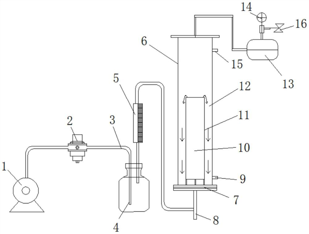
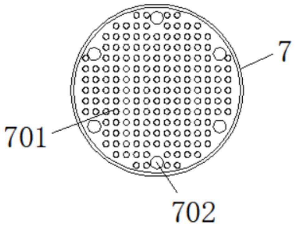
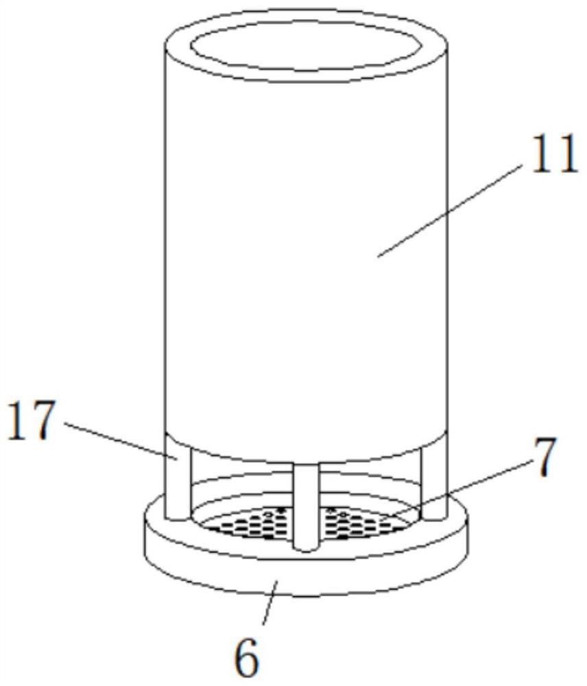
[0035] see figure 1 , 2, 4 and 5, a kind of technology that adopts foam separation tower to treat surfactant wastewater, experiment adopts simulated surfactant wastewater cetyltrimethylammonium bromide (CTAB) aqueous solution as system, concentration is 100mg / L, experiment For intermittent operation, the treatment capacity of each batch of wastewater is 350mL; the pH value of the solution is adjusted by adding HCl or NaOH to the simulated industrial wastewater; the surfactant wastewater solution is injected from the top of the tower body through the sampling port 15, and the liquid volume is high 350mm, gas velocity = 300mL / min, the temperature of the experiment is maintained at (22 ± 1) ° C, the liquid sample is collected from the sampling port 15 on the side; the internal circulation flow foam separation tower 6 operates the system, including the air compressor 1 and the pressure stabilizing valve 2. Conduit 3, gas buffer bottle 4, rotameter 5, foam separation tower 6, gas ...

specific Embodiment 2

[0041] see Figure 1-6 , a process for treating surfactant wastewater using a foam separation tower. The experiment uses a simulated surfactant wastewater cetyltrimethylammonium bromide (CTAB) aqueous solution as the system, and the CTAB concentration is 3.0g L -1 , the experiment is intermittent operation, and the treatment capacity of each batch of wastewater is 350mL; the pH value of the solution is adjusted by adding HCl or NaOH in the simulated industrial wastewater; the surfactant wastewater solution is injected from the top of the tower body through the sampling port 15, and the liquid is filled The measurement height is 350mm, the gas velocity=300mL / min, the temperature of the experiment is maintained at (22 ± 1) ℃, and the liquid sample is collected from the sampling port 15 on the side; the operating system of the internal circulation foam separation tower 6 includes an air compressor 1, a stable Pressure valve 2, conduit 3, gas buffer bottle 4, rotameter 5, foam sep...


PUM

PropertyMeasurementUnit
diameteraaaaaaaaaa
diameteraaaaaaaaaa

Abstract

The invention discloses a process for treating surfactant wastewater by using a foam separation tower. The process comprises an air compressor, a foam separation tower and an inner sleeve, the output end of the air compressor is connected with a pressure stabilizing valve, the output end of the pressure stabilizing valve is connected with a gas buffer bottle, the top end of the foam separation tower is connected with a foam liquid collecting box, and the outer side of the foam liquid collecting box is connected with an adjusting valve, and one side of the adjusting valve is connected with a pressure gauge. The gap between the sleeve and the tower wall of the foam separation tower can form an effective circulation, liquid in the sleeve moves upwards under the action of gas, and liquid in the gap between the sleeve and the tower wall flows downwards; the tiny bubbles are entrained in circulating liquid due to small buoyancy and cannot leave the liquid level to reach a foam layer; in this way, the bubbles forming the foam layer are all large bubbles; and the liquid holdup of foam formed by larger bubbles is lower, so that the enrichment ratio of foam separation is improved.

Description

technical field [0001] The invention relates to the technical field of active agent wastewater treatment, in particular to a process for treating surfactant wastewater by using a foam separation tower. Background technique [0002] Surfactants have excellent wetting, foaming, emulsifying, decontaminating, dispersing and penetrating properties, and their application fields are still expanding. While surfactants provide functions and support to various production industries, they also bring pollution to life. At present, most of the surfactants are discharged into natural water bodies such as rivers and oceans without proper treatment after use, causing water pollution. Surfactants in wastewater will form a large number of foams in the water body, which not only affects the appearance of the water body, but also Reduce the concentration of dissolved oxygen in the water body; when the water body is severely hypoxic, it will cause difficulty in breathing for aquatic organisms, ...

Claims


Application Information

Patent Timeline
Patent Type & Authority Applications(China)
IPC IPC(8): C02F1/24C02F101/36
CPCC02F1/24C02F2101/36C02F2301/08
Inventor 申秋华李瑞王晓杰韩冰
Owner 中国人民解放军海军勤务学院
Why Eureka
Try Eureka