
Rate 32/33 (D=0, K=6) run length limited modulation code having optimized error propagation

a technology of run length and modulation code, applied in the direction of code conversion, recording signal processing, instruments, etc., can solve the problems of affecting the instantaneous change of angular velocity, the relatively low mass of moving recording tapes, and the inability to realize the practical hardware implementation of encoding and decoding processes

Inactive Publication Date: 2001-02-06
QUANTUM CORP
View PDF2 Cites 29 Cited by
  • Summary
  • Abstract
  • Description
  • Claims
  • Application Information

AI Technical Summary

Benefits of technology

Another object of the present invention is to provide a practical rate 32 / 33 modulation code and implementation which achieves a very high code rate without sacrificing reliability of detected data in a manner overcoming limitations of prior approaches.
A further object of the present invention is to provide simplified, reliable encoding and decoding methods for encoding 32 bit data words into 33 bit code words in consonance with predetermined modulation coding constraints, including minimum zero run length, and maximum zero run length and in a manner effectively limiting error propagation.

Problems solved by technology

One drawback of a canonical target of form (1-D)(1+D).sup.N is that it is only an approximate match to the magnetic channel but is relatively easily implemented; and it manifests a spectral null at the Nyquist sampling frequency.
One difficulty arising from the adoption of a very high rate modulation code is the considerable complexity usually required to realize practical hardware implementations of the encoding and decoding processes.
Tape recording differs from rigid disk recording in that moving recording tape has relatively very low mass and is susceptible to substantial variation in instantaneous tape velocity.
On the other hand, one or more rigid recording disks mounted to a rotating spindle manifest substantial angular momentum which impedes instantaneous change in angular velocity.
Further, tape that has been spooled in e.g. a relatively dry or humidity-free environment and later stored for a time in a high humidity environment may experience constrained expansion from absorption of moisture, leading to unpredictable behavior causing sharp velocity differentials as the tape is fed from the spool.
When errors occur in the detection process they can be further propagated into more errors in passing through the modulation decoder.
Therefore, a hitherto unsolved need has remained for a very high rate modulation code for a magnetic recording channel which meets the foregoing requirements and solves the problems associated with the prior approaches.

Method used


Image

  • Rate 32/33 (D=0, K=6) run length limited modulation code having optimized error propagation
  • Rate 32/33 (D=0, K=6) run length limited modulation code having optimized error propagation
  • Rate 32/33 (D=0, K=6) run length limited modulation code having optimized error propagation

Examples


case 1

lations in U (59% likelihood of occurrence (upon the assumption that ones and zeros are equally likely to occur at the input to the modulation encoder)). The FLAG variable is set equal to 00000000. The control bit of code sub-word c5, i.e. c5[0], is set equal to one and the remaining nibbles are passed unencoded. Thus, c7 equals u7, c6 equals u6, c5[5-1] equals u5, c4 equals u4, c3 equals u3, c2 equals u2, c1 equals u1 and c0 equals u0.

case 2

olation in U (31.8% likelihood of occurrence). The FLAG variable is set equal to one of {00000001, 00000010, 00000100, . . . 10000000 } depending upon the location of the nibble containing the code violation. The bits c5[0] and c5[2] are set to be equal to zero and one respectively. The remaining c5 bits are used to indicate in which of the eight locations the single violation occurred. For example, if FLAG indicates that the third low order nibble u2 contained the single code violation (FLAG=00000100), then c5[0]=0, c5[2]=1, and c5[4:3, 1]=010 to indicate that the third nibble u2 contains four zeros. Since the nibble c5 is used to indicate in this example that the nibble u2 is all zeros, the information in user nibble u5 is mapped into the third code nibble position c2. Encoding is completed as c7 equals u7, c6 equals u6, c5 equals [01110], c4 equals u4, c3 equals u3, c2 equals u5, c1 equals u1 and c0 equals u0.

case 3

olations in U (7.4% likelihood of occurrence). The FLAG variable has two bit positions set, e.g. {00000011, 00000101, . . . 11000000}. The bits c5[0] and c5[2] are set to zero, and the bit c4[3] is set to one. The remaining c5 bit positions are used to indicate in which of the eight locations the left side violation occurred, and the bits c4[2:0] indicate the nibble position of the right side violation. For example, if violations occurred in nibbles u7 and u0, FLAG is equal to 10000001, and c5[0] equals zero, c5[2] equals zero, c4[3] equals 1, c5[4:3,1] equals 111 and c4[2:0] equals 000. Since the user nibble u7 is all zeros, the nibble c5 is used to indicate that nibble u7 is all zeros, and the information in nibble u5 is mapped into c7 (i.e. the 8th code nibble). Similarly, the information in user nibble u4 is mapped into cO (the first code nibble). The final encoding of this example is therefore c7 is equal to u5, c6 is equal to u6, c5 is equal to [01100], c4 is equal to [1000], ...


PUM

PropertyMeasurementUnit
zero run lengthaaaaaaaaaa
run lengthaaaaaaaaaa
sizeaaaaaaaaaa

Abstract

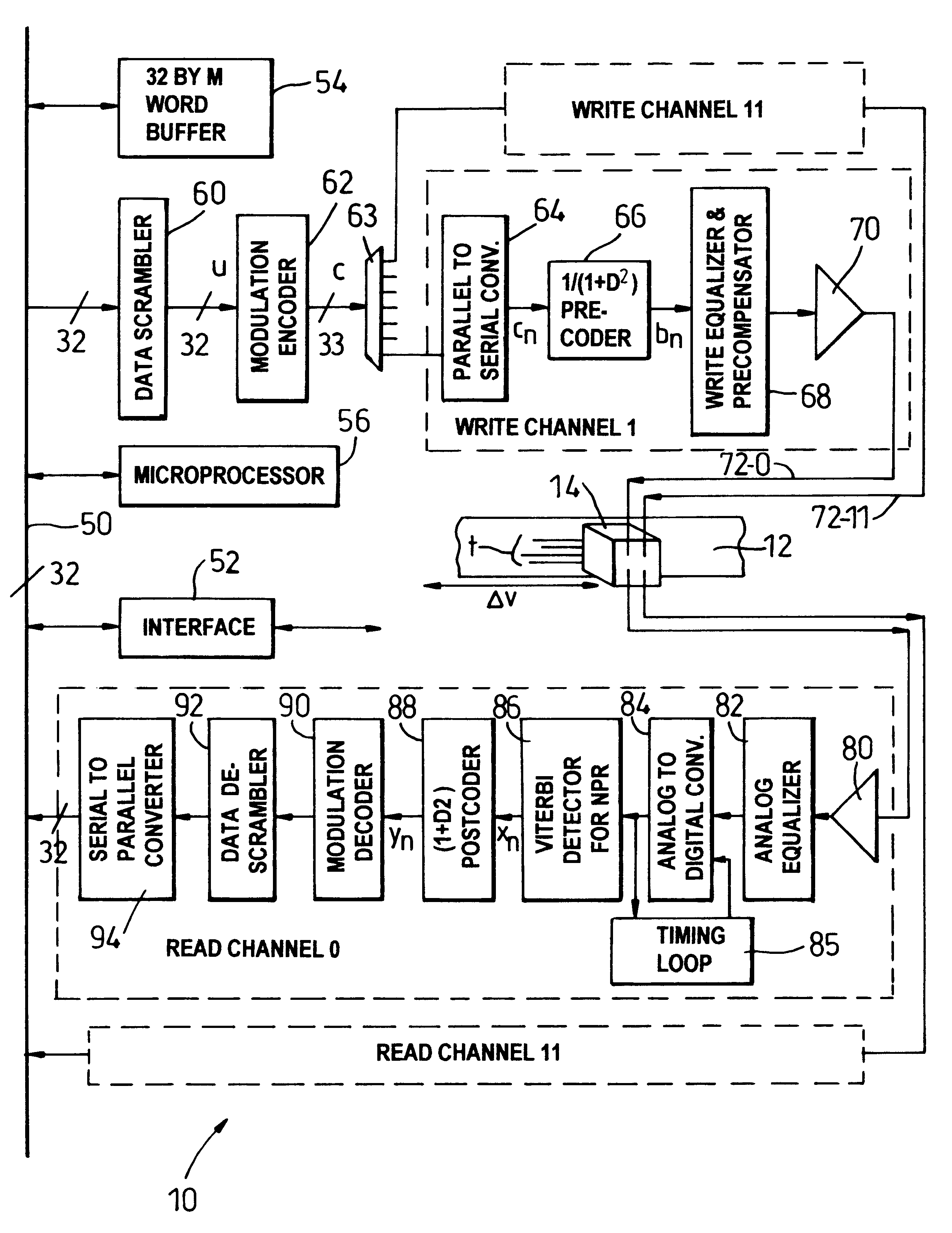
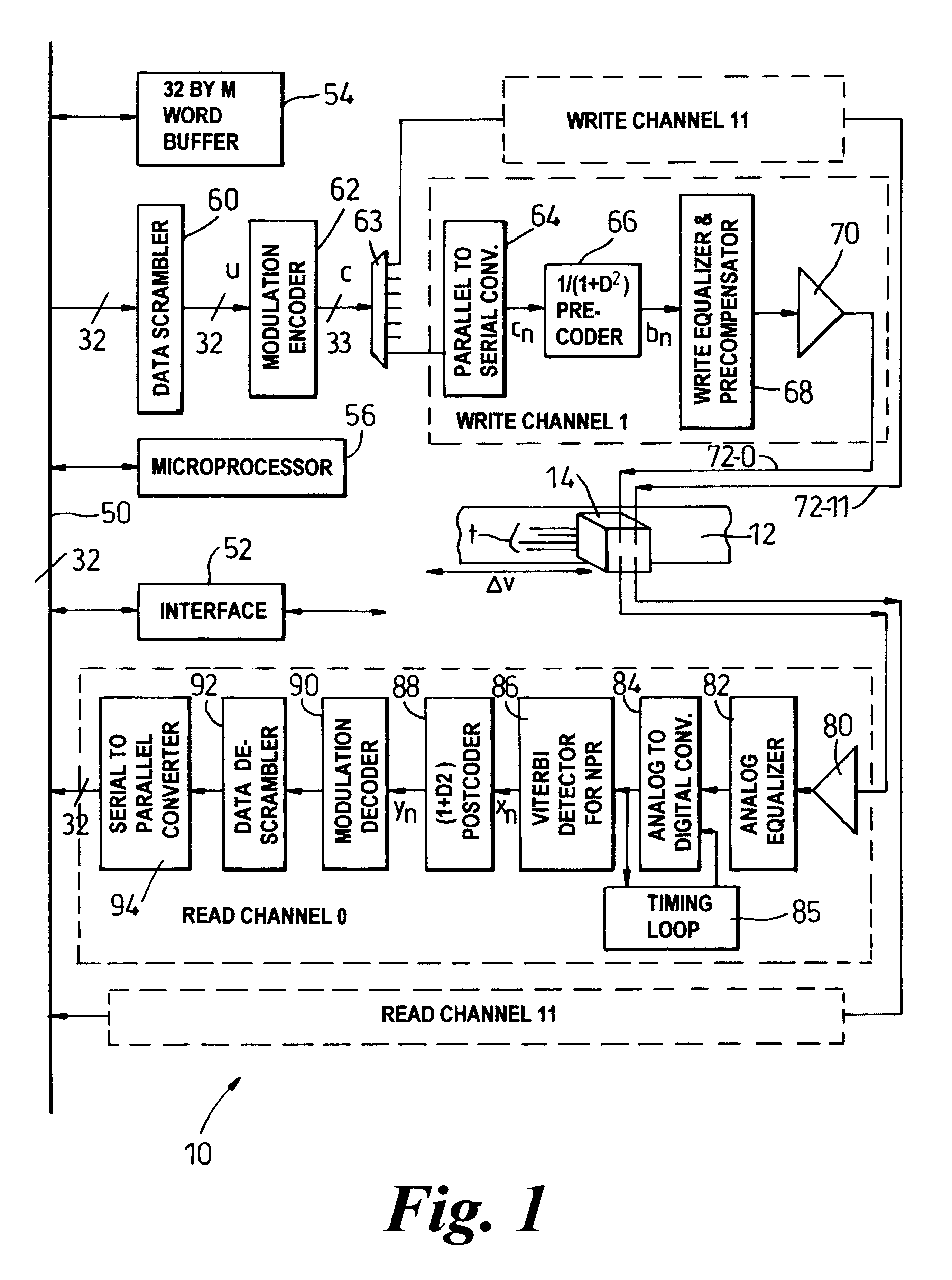
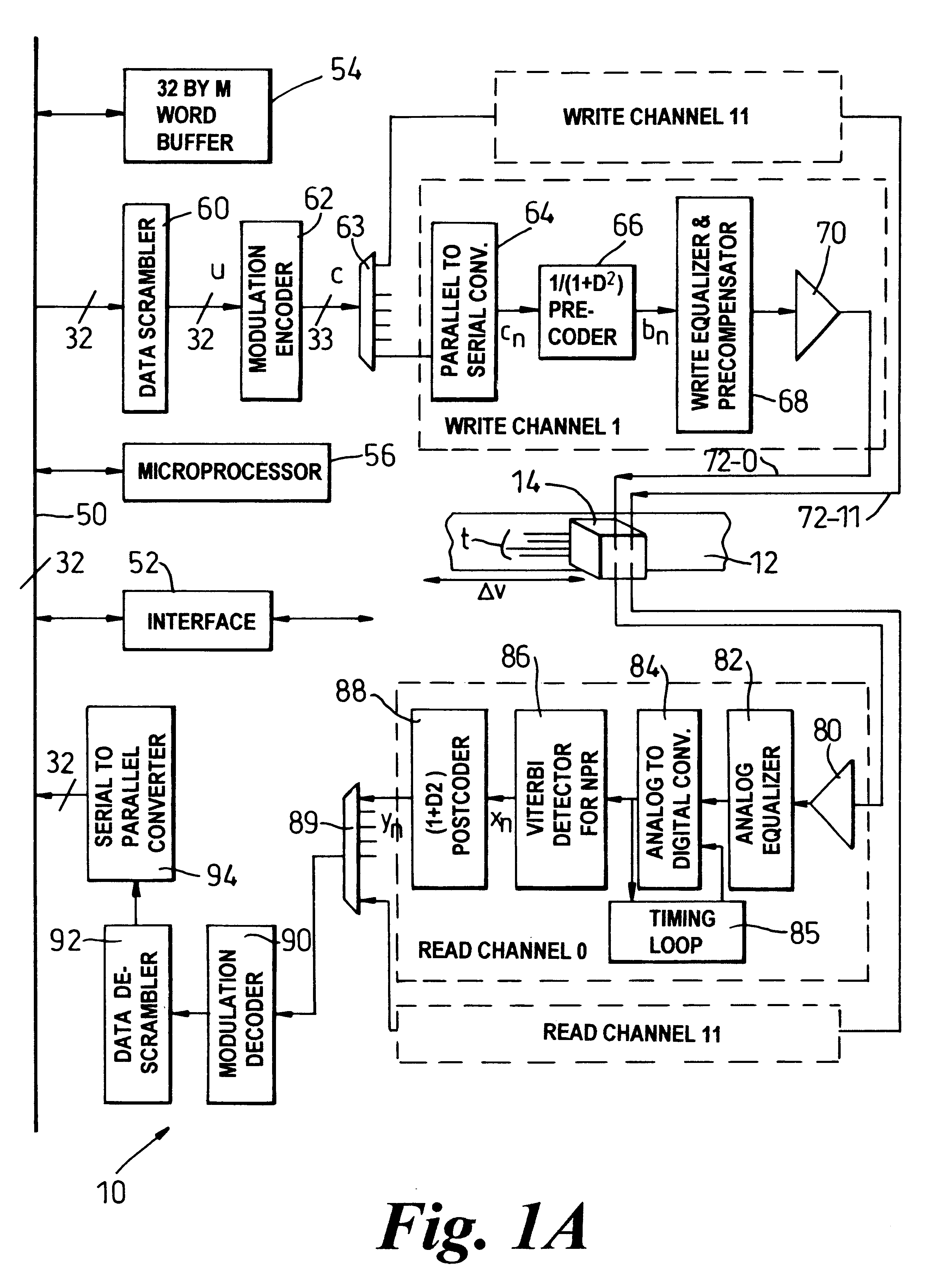
A method and apparatus for encoding a sequence of 32 bit digital data words into a sequence of 33 bit code words in consonance with predetermined minimum zero run length (d) and predetermined maximum zero run length (k) for recording upon a magnetic medium within a magnetic recording channel is disclosed. The method comprises steps of dividing each data word into eight data nibbles, determining whether any data nibble contains all zeros. If no code violation, mapping the eight data nibbles to seven code nibbles and to four bits of a five bit code sub-word and setting a fifth control bit to one. If one or more code violations are present, embedding code violation locations within at least the five bit code sub-word and other code nibbles if necessary and remapping data nibbles ordinarily directed to the code sub-word and nibble locations to code locations otherwise containing the data nibbles determined to be code violations.

Description

The present invention relates to modulation codes, methods and modulation encoding / decoding apparatus. More particularly, the present invention relates to a high rate run length limited modulation code with a small maximum run length (e.g. k=6), with optimized error propagation properties and with a simple implementation within a magnetic recording system, such as a digital linear magnetic tape recording and playback system.Modulation codes have been employed within magnetic recording channels in order to achieve a more even distribution of magnetic flux transitions within a data track in view of data patterns of particular user information being encoded and recorded. In particular, run length limited (RLL) modulation codes have been employed within partial response, maximum likelihood sampling detection (PRML) data recording and playback channels, decision feedback equalization (DFE) detection channels, and fixed delay tree search (FDTS) detection channels.Canonical partial respons...

Claims


Application Information

Patent Timeline
Patent Type & Authority Patents(United States)
IPC IPC(8): G11B5/09H03M5/00H03M5/14G11B20/10G11B20/14H03M7/14
CPCG11B5/09H03M5/145G11B20/10009G11B20/10055
Inventor PATAPOUTIAN, ARASTANDER, JENNIFERMCEWEN, PETERZAFER, BAHJATFITZPATRICK, JAMES
Owner QUANTUM CORP
Learn More