Radiant floor heating system with reflective layer and honeycomb panel

a technology of reflective layer and honeycomb, which is applied in the direction of fluid heaters, heating types, lighting and heating apparatus, etc., can solve the problems of substantial heat waste, and achieve the effect of preventing heat dispersal

Inactive Publication Date: 2001-02-13
PENNELLA RONALD J
View PDF28 Cites 65 Cited by
  • Summary
  • Abstract
  • Description
  • Claims
  • Application Information

AI Technical Summary

Benefits of technology

An additional object of the invention is to provide a reflective surface layer that reflects heat from a heating element upwards toward the flooring material thus preventing dispersal of heat below the reflective surface.

Problems solved by technology

As such, a substantial amount of heat is wasted.

Method used


Image

  • Radiant floor heating system with reflective layer and honeycomb panel
  • Radiant floor heating system with reflective layer and honeycomb panel
  • Radiant floor heating system with reflective layer and honeycomb panel

Examples


Embodiment Construction

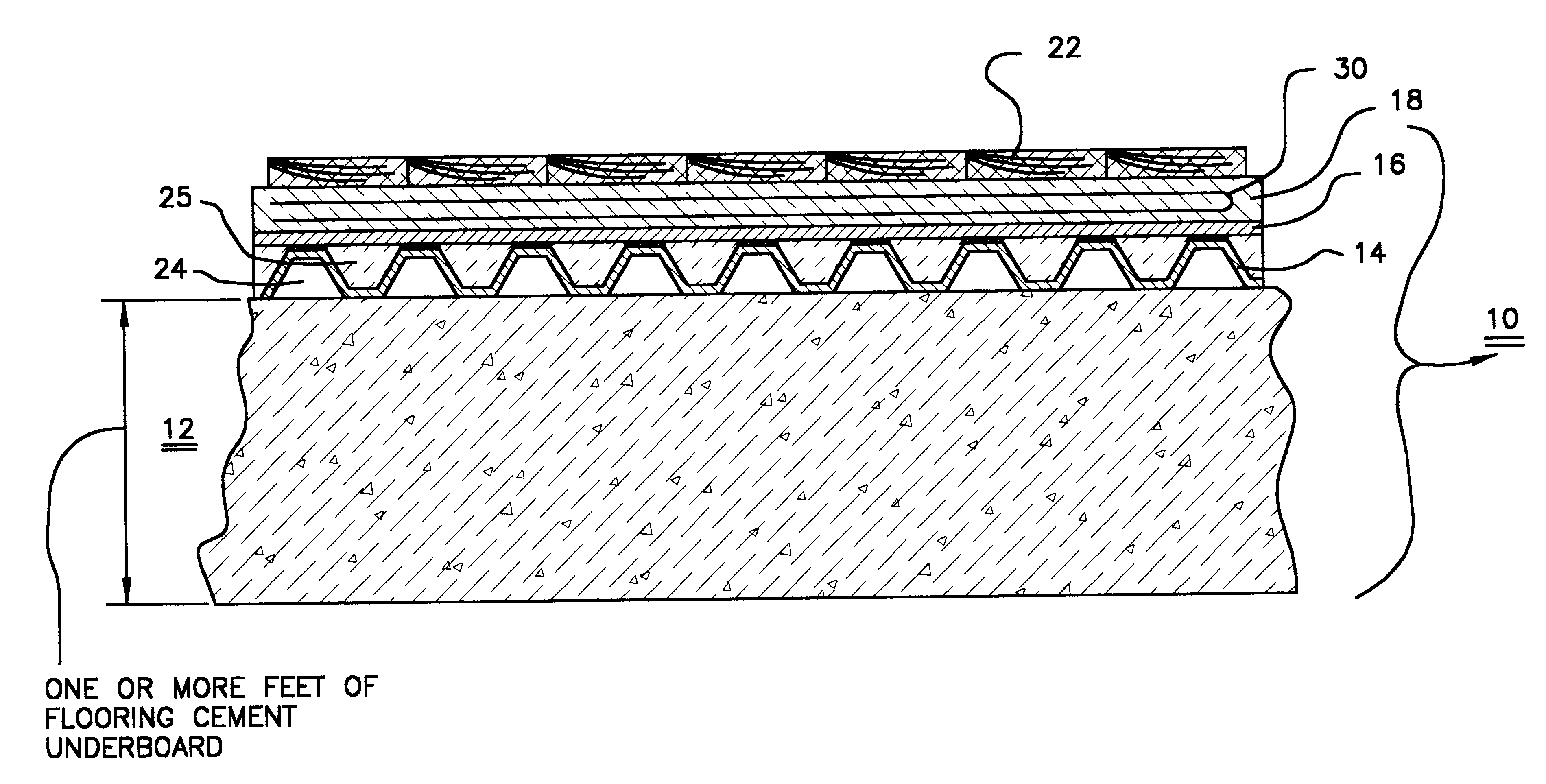
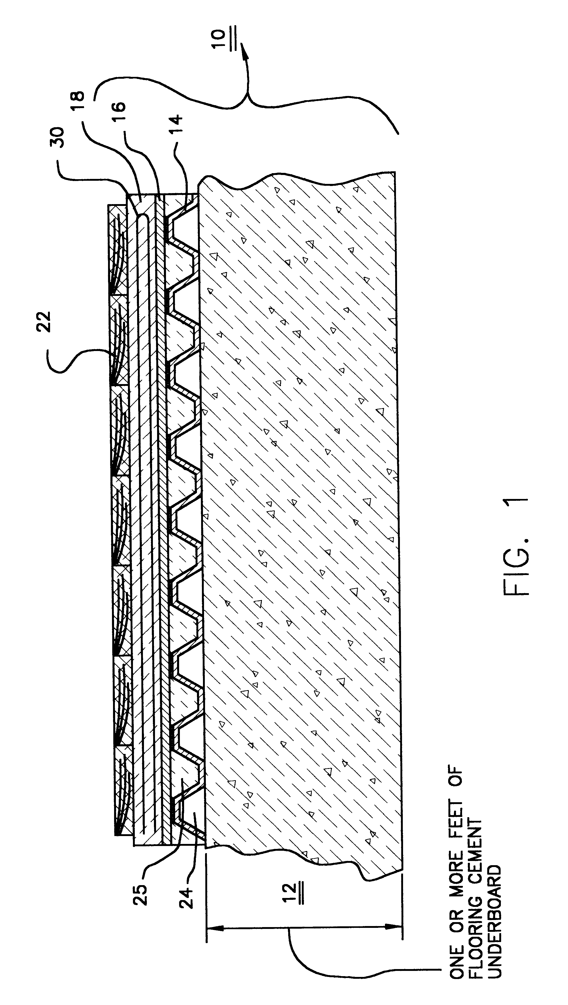
With initial reference to FIG. 1, a radiant floor heating system 10 and method of installation as installed on a sub-flooring 12 is shown and provided. The radiant floor heating system 10 is provided with a barrier or panel member 14 on which a reflective surface 16 is mounted. A heating element 30 is secured to the reflective surface 16 and then coated with a layer of wet thin set or self-leveling cement 18. In this way, the heating element 30 is imbedded within the self-leveling cement 18. After the self leveling cement 18 dries with the heating element embedded within, flooring tiles 22 may be laid as flooring.

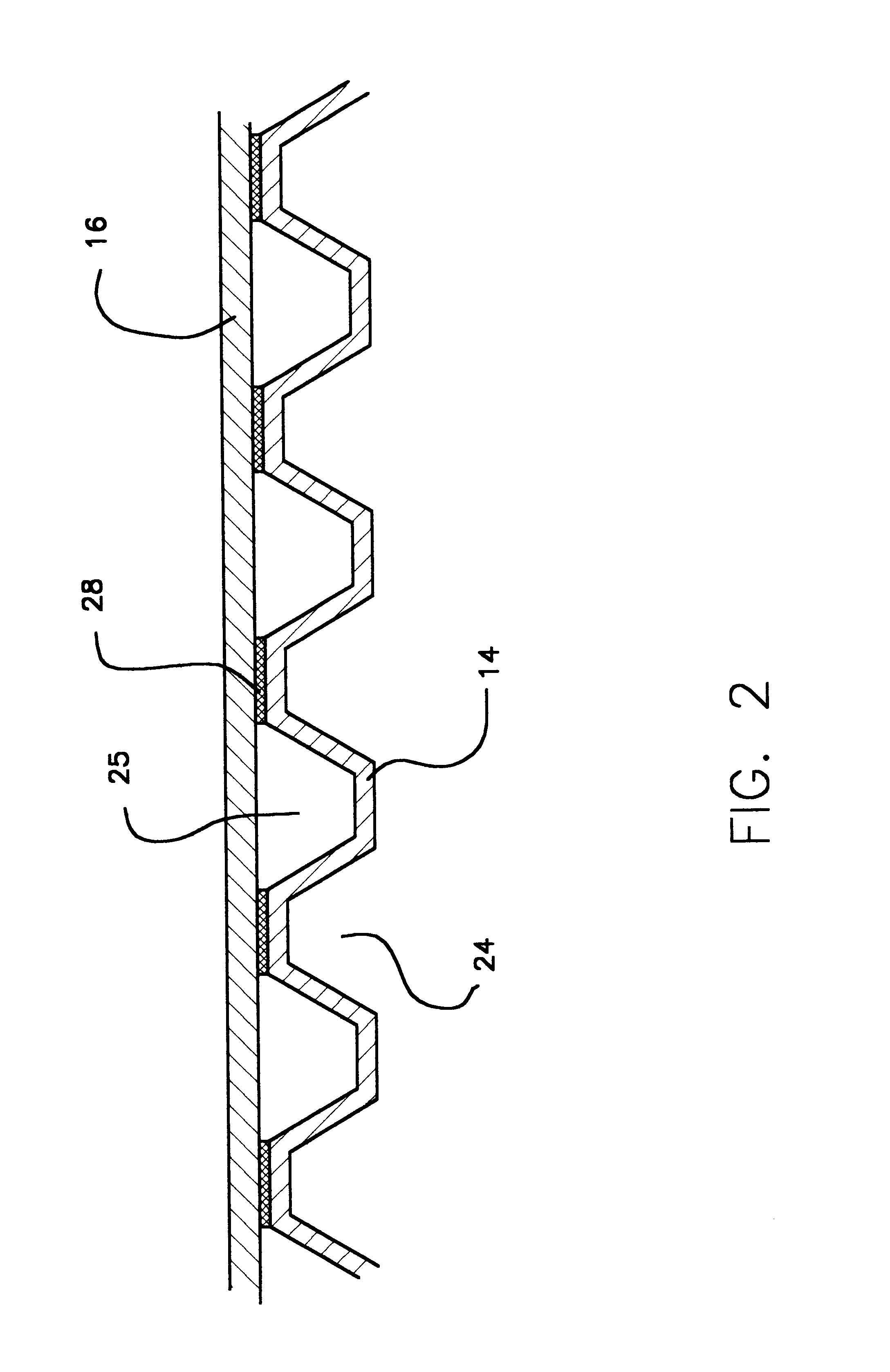
As shown in FIG. 2, the panel member 14 is shown bonded to reflective surface 16. With specific reference to the panel member 14, panel member 14 comprises a honeycombed plastic panel such as a NorCore brand horizontal flooring as manufactured by the Norfield Corporation of Danbury, Conn. The horizontal flooring provides a high strength to weight ratio such physical propert...


PUM


Abstract

A radiant floor heating system and method of installation is provided, the system of the present invention being disposed within a solidified cement or under board. A panel member having a laminated reflective material which serves as a thermal break is placed upon the hardened cement or under board. The panel member may be comprised of any substance to which the reflective material may be secured such as a honeycombed plastic panel to which the reflective material layer is laminated. A heating element is disposed on the reflective material. Thereafter, both the heating element and the reflective layer are coated with a layer of thin set or cement. The heating element may include a heated wire element which is unwound off a roll, or the heating element may be meshed within a web of material which is cut to match the dimensions of the floor and then disposed on top of the reflective layer. After the thin set or cement dries with the heating element embedded within, marble or other types of tiles may be laid as flooring.

Description

This invention relates to a floor heating system and method of installation and more specifically, to a system which utilizes a thermal barrier having an attached reflective material for directing heat upwards from beneath a floor heating element so as to increase the efficiency of a heating system.In heating the interiors of buildings and of building floors, several conventional heating methods have been employed, including hot water / steam and forced air heating. Generally, these heating methods require the installation of large air ducts or extensive water piping, both of which take up a considerable amount of space within a building and require careful planning for locations of vent, radiators and so forth. Vents and ducts tend to obstruct living and working areas within a building and require other components of the building (ceilings, walls, etc.) to be designed around them. Some hot water systems include piping which is embedded in a flooring or ceiling material through which ...

Claims


Application Information

Patent Timeline
Patent Type & Authority Patents(United States)
IPC IPC(8): F24D13/02
CPCF24D13/02Y02B30/26Y10T428/24149Y02B30/00
Inventor PENNELLA, RONALD J.
Owner PENNELLA RONALD J
Why Eureka
Try Eureka