Scanning force microscope and method for beam detection and alignment

a scanning force microscope and beam detection technology, applied in the direction of instruments, mechanical roughness/irregularity measurements, measurement devices, etc., can solve the problems of limited force capability of lateral and vertical drive mechanisms, small change in the angle of the free end of the cantilever, and many alternate techniques have limits of their own

Inactive Publication Date: 2001-02-20
RAYMAX TECH
View PDF28 Cites 12 Cited by
  • Summary
  • Abstract
  • Description
  • Claims
  • Application Information

AI Technical Summary

Benefits of technology

(a) the mass of the moving portion of the microscope is reduced;
(c) the laser beam adjustment is simple and the method is easily implemented;
(d) visual access to the probe assembly is improved; and

Problems solved by technology

However, many of these alternate techniques have limits of their own and may have other disadvantages in implementation such as a need to place the sample in a vacuum chamber.
This results in a slight change in the angle of the free end of the cantilever.
This method has a disadvantage stemming from the limited force capability of the lateral and vertical drive mechanisms.
The mass associated with moving part of such microscopes limits the speed at which the image data can be taken.
The result is a significant limit to the velocity of the stylus over the sample.
This is caused either by wear or by small particles which become attached to the stylus as it scans over the sample.
Also the stylus may break.
The scanning mechanism often consist of thin walled piezoelectric tubes which are quite fragile.
The operator may apply too much force when adjusting the probe lateral adjustment mechanism thus damaging or breaking the tube.

Method used


Image

  • Scanning force microscope and method for beam detection and alignment
  • Scanning force microscope and method for beam detection and alignment
  • Scanning force microscope and method for beam detection and alignment

Examples


Embodiment Construction

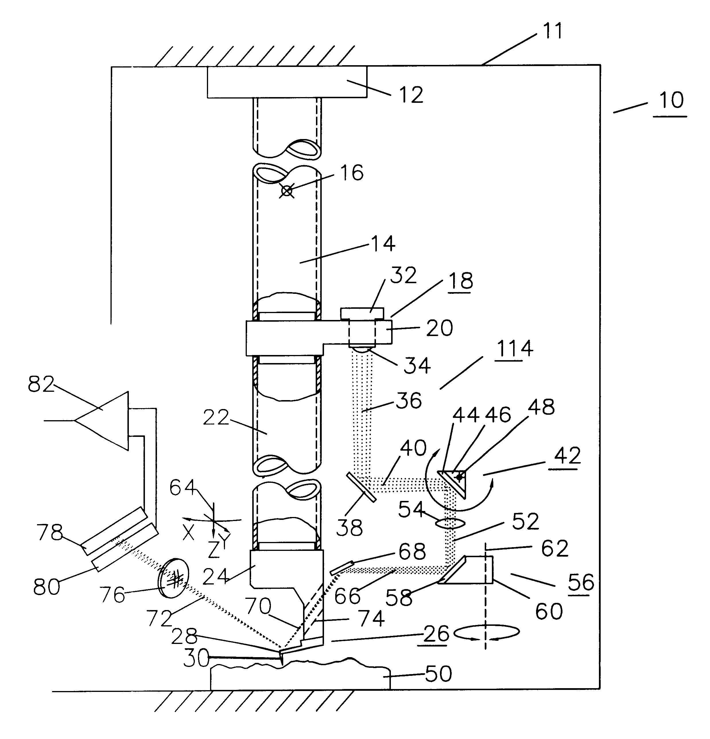
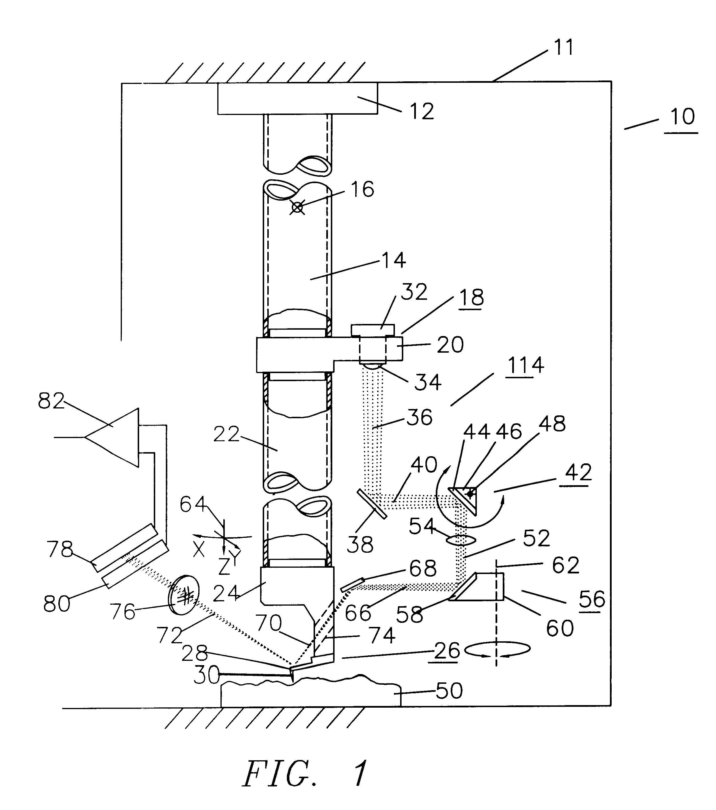
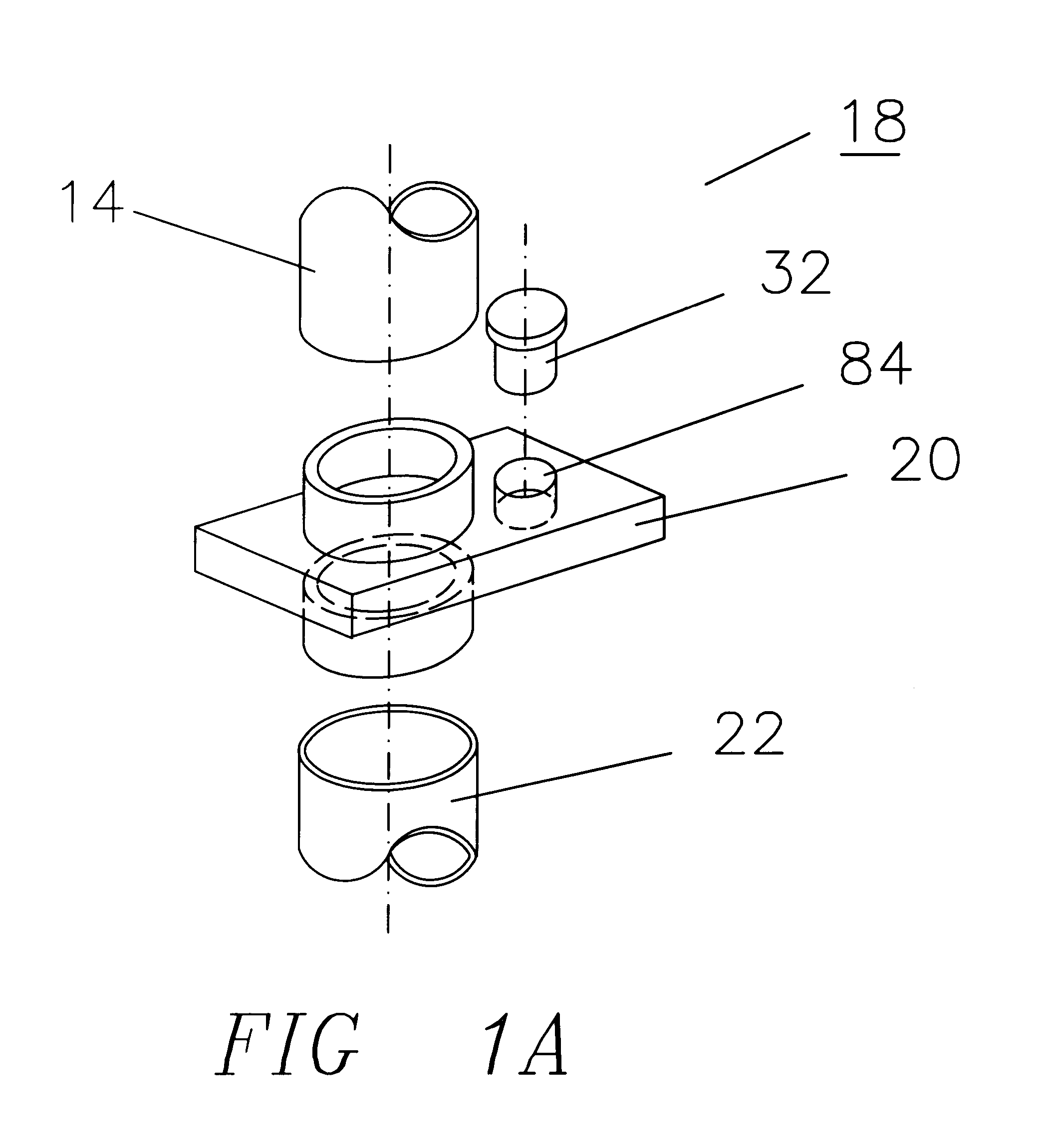
A preferred embodiment of the invention is given in FIG. 1. A microscope 10 has a fixed reference frame 11. A scanner mount 12 attaches a lateral driver 14 to fixed reference frame 11. Lateral driver 14 may be in the form of a piezoelectric tube with electrodes (not shown). The free end of lateral driver 14 appears to rotate around a mechanical pivot 16. Mechanical pivot 16 is located approximately at the mid point between the fixed and free end of lateral driver 14. A laser coupler assembly 18 couples the free end of lateral driver 14 to the upper end of a vertical driver 22 and also carries a laser 32 in the x and y directions. Laser 32 has a focusing lens 34 which produces a converging beam of light with a first segment 36.

Vertical driver 22 may be a piezoelectric tube with electrodes (not shown). A probe assembly holder 24 is connected to the lower end of vertical driver 22 and supports a probe assembly 26. First beam segment 36 impinges on a first fixed mirror 38 resulting in a...


PUM


Abstract

A scanning force microscope (10) sometimes referred to as an atomic force microscope employs a laser (32) and a cantilever (28) which move proportionally to a moving reference frame (64). A fixed reference frame (11) contains optical components. A scanning mechanism creates relative movement between the fixed and moving reference frames. An optical assembly (114) is included which comprises at least one optical device in the fixed reference frame. The optical assembly permits initial alignment of the laser beam onto the cantilever and also permit the laser beam to follow the moving cantilever.

Description

1. Field of the inventionThis invention relates to scanning force microscopes, sometimes referred to as atomic force microscopes, using light beam detection schemes.2. Description of Prior ArtConventional optical microscopes used to observe the surface features of materials begin to lose resolution when the dimensions of the surface features approach one half the wavelength of visible light. Alternate types of microscopes have been developed to overcome this limit. Confocal microscopes, for example, can improve on conventional optical limits. Scanning electron microscopes image small surface features by the use of energized electrons that have wavelengths shorter than photons. However, many of these alternate techniques have limits of their own and may have other disadvantages in implementation such as a need to place the sample in a vacuum chamber.A new class of microscopes overcomes the resolution limits of previous techniques in a fairly simple manner. Microscopes in this class a...

Claims


Application Information

Patent Timeline
Patent Type & Authority Patents(United States)
IPC IPC(8): G01B5/28G01B21/30G01Q20/02G01Q60/38
CPCB82Y35/00G01Q20/02G01Q60/38Y10S977/87
Inventor RAY, DAVID J.
Owner RAYMAX TECH
Why Eureka
Try Eureka