Tribometer for testing the efficiency of lubrication upon a railroad track surface

a technology for lubricating efficiency and railroad tracks, applied in the direction of mechanical measuring arrangements, mechanical roughness/irregularity measurements, instruments, etc., can solve the problems of inability to easily relocate, compare raw data, and use of expensive monitoring instruments

Inactive Publication Date: 2001-02-27
DIVERSIFIED METAL FABTORS
View PDF18 Cites 31 Cited by
  • Summary
  • Abstract
  • Description
  • Claims
  • Application Information

AI Technical Summary

Problems solved by technology

These drawbacks included: the use of instrumentation that was usually "hard wired" to a single site and thus could not be easily relocated; the use of instrumentation that both was expensive to monitor, and required several iterations of data reduction; the comparison of raw data between different sites (before adjusting for train influences), which was difficult, if not impossible; and, the need for specific train makeup and input information such as train speed, car weight, car type, wheel profile, and recent braking history, all of which had a major effect on results, requiring careful interpretation of the data, and which made accurately determining lubrication effectiveness extremely difficult.
When a railway car passes over the contact block, any frictional wheel drag, which can be caused by a defect in the axle journal bearings, will cause the contact block to rotate in the direction of movement of the car.
Since they are hand-operated devices, the speed of testing and the length of rail tested are limited to the walking speed and range of the track inspector.
These devices also can weigh up to 45 pounds, making long inspection sessions difficult.
They include, among others: (1) the problem of the build up of lube, dirt, and grease in and around the device which prevents accurate measurements; (2) the problem of interference from communications equipment, for example, the operation of two-way radios and cellular phones, which can interfere with the operation of an automated tribometer, including the data collection; and (3) the disruption in operation of the apparatus upon the build up of ic

Method used


Image

  • Tribometer for testing the efficiency of lubrication upon a railroad track surface
  • Tribometer for testing the efficiency of lubrication upon a railroad track surface
  • Tribometer for testing the efficiency of lubrication upon a railroad track surface

Examples


Embodiment Construction

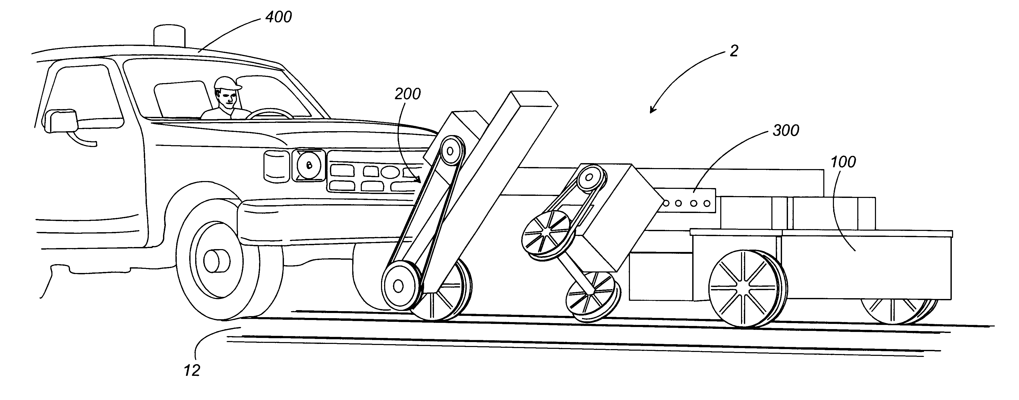
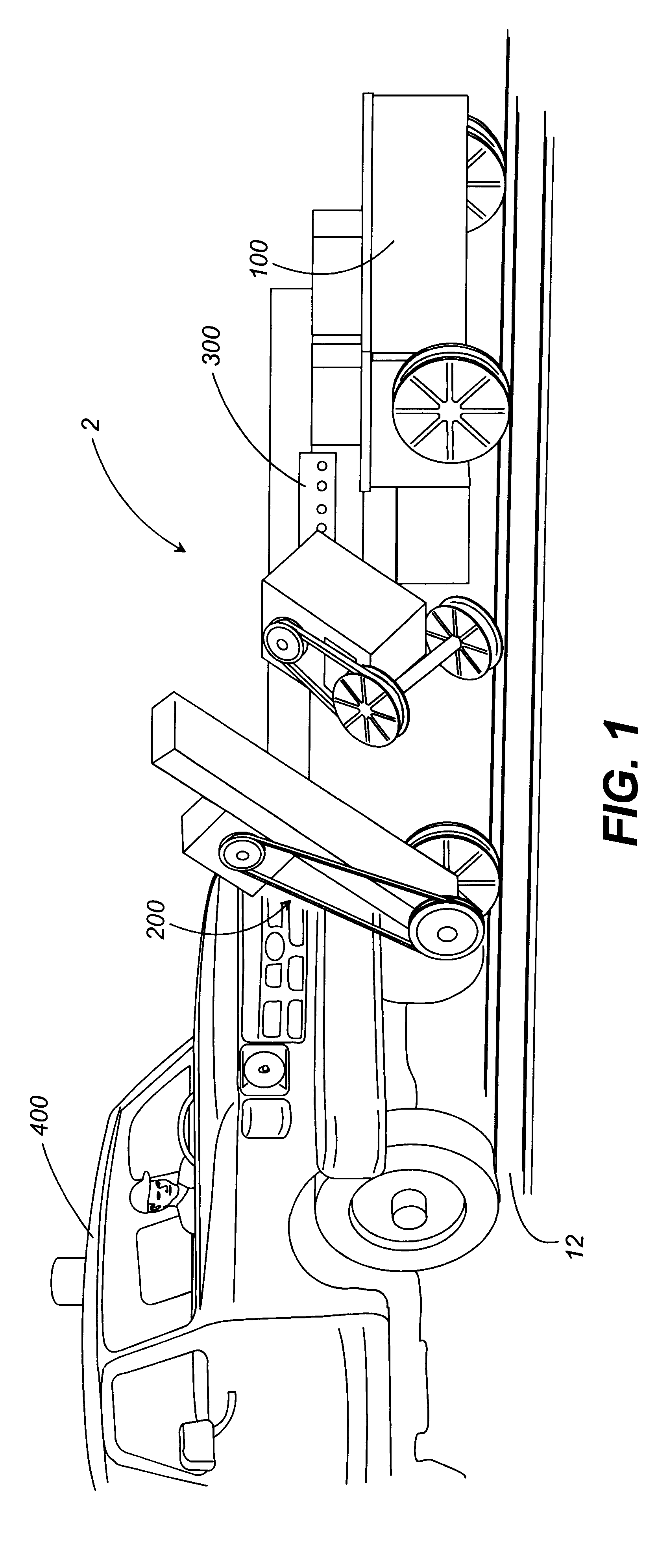
Referring now in detail to the drawing figures, wherein like reference numerals represent like parts throughout the several views, as shown in FIG. 1 the tribometer 2 of the present invention preferably comprises a test cart 100, an attachment means 200 to attach the test cart 100 to a motive means to propel the test cart 100 down the railroad track 12, and automated systems 300 to control the operation of the test cart 100 and measure the various data of the rails, including the COF data.

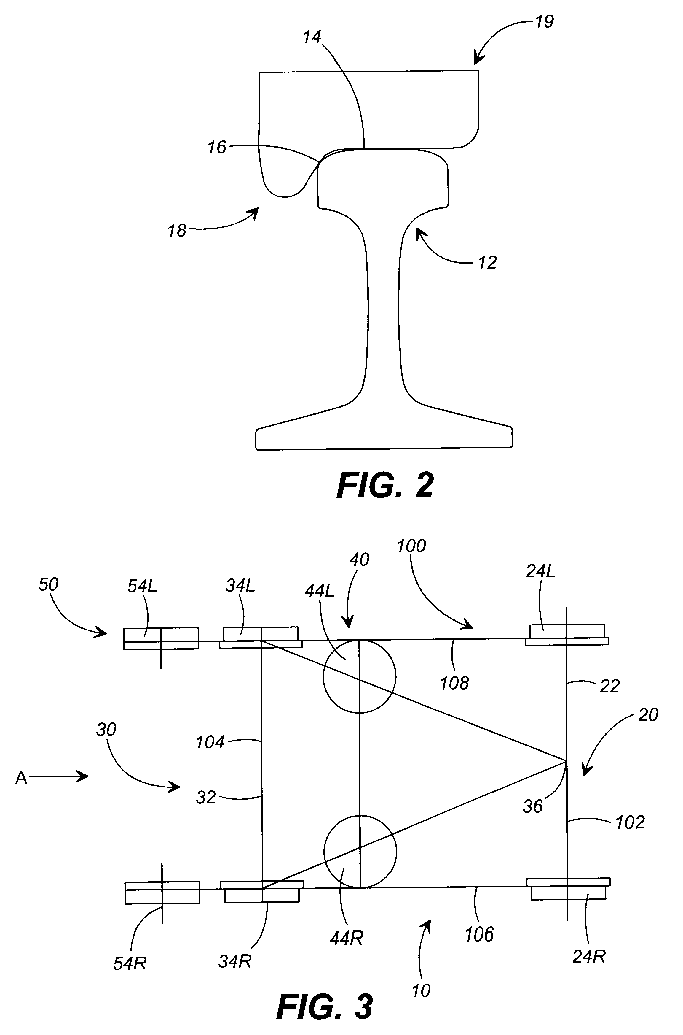
The tribometer 2 is designed to ride along the surface of railroad rails 12 and measure and record data relating to rail lubrication, including data representative of the coefficient of friction of preferably the rail 12 running surface 14 and the rail 12 gauge surface 16 of both rails. FIG. 2 shows a cross section of a single rail 12. The rail 12 is the right rail of a two rail track if the direction of forward travel is into the drawing figure. In this configuration, the flange portion 18 of a ty...


PUM


Abstract

An automated tribometer for measuring the coefficient of friction of the tread and gauge surfaces of railroad rail is disclosed. A tribometer is provided that is pushed in front of a high-rail vehicle, wherein during operation, the tribometer extends a rail test assembly to contact the surfaces of the rail. The rail test assembly has a rail testing wheel that is urged towards contact with the rail to be tested, and eventually contacts the rail, and lastly applies a known load to the rail. The testing wheel is then dynamically braked to slow the testing wheel to the point of creepage. The automated tribometer then can calculate the coefficient of friction of the rail.

Description

1. Field of The InventionThe invention relates generally to an apparatus for measuring the coefficient of friction (COF) of a surface. In particular, the present invention relates to an apparatus for measuring the coefficient of friction of a surface of a railroad rail. The invention provides a tribometer with standard train wheels (cart wheels) that is either pushed in front of a hi-rail vehicle, or pulled by a track geometry car (or rail vehicle), which measures and records data representative of the coefficient of friction of the rail tread surface and the rail gauge surface of railroad rails. The tribometer has testing wheels, and uses "dynamic braking" to slow the testing wheels to the point of creepage, that is, just prior the point of slippage of the testing wheels upon the rails. The tribometer calculates the speed of the tribometer's testing wheels and compares it to the speed of the tribometer's cart wheels to calculate the creepage torque on the testing wheels. The creepa...

Claims


Application Information

Patent Timeline
IPC IPC(8): B61K9/00B61K9/08G01N19/02
CPCB61K9/08G01N19/02
Inventor CLEM, GEORGE K.
Owner DIVERSIFIED METAL FABTORS
Why Eureka
Try Eureka