Mounting structure for a relay arranged on a printed circuit board

a technology of printed circuit board and mounting structure, which is applied in the direction of relays, printed circuit non-printed electric components association, electrical apparatus construction details, etc., can solve the problems of increasing cost, easy to be further absorbed, and difficult to remain heat in resin blocks

Inactive Publication Date: 2001-02-27
YAZAKI CORP
View PDF17 Cites 32 Cited by
  • Summary
  • Abstract
  • Description
  • Claims
  • Application Information

AI Technical Summary

Problems solved by technology

However, this causes a problem of increasing cost.
Also, since the bus bar extends to both sides in the width direction of the resin block, a heat is hard to remain in the resin block, and the heat is easy to be further absorbed through the bus bar.

Method used


Image

  • Mounting structure for a relay arranged on a printed circuit board
  • Mounting structure for a relay arranged on a printed circuit board
  • Mounting structure for a relay arranged on a printed circuit board

Examples


first embodiment

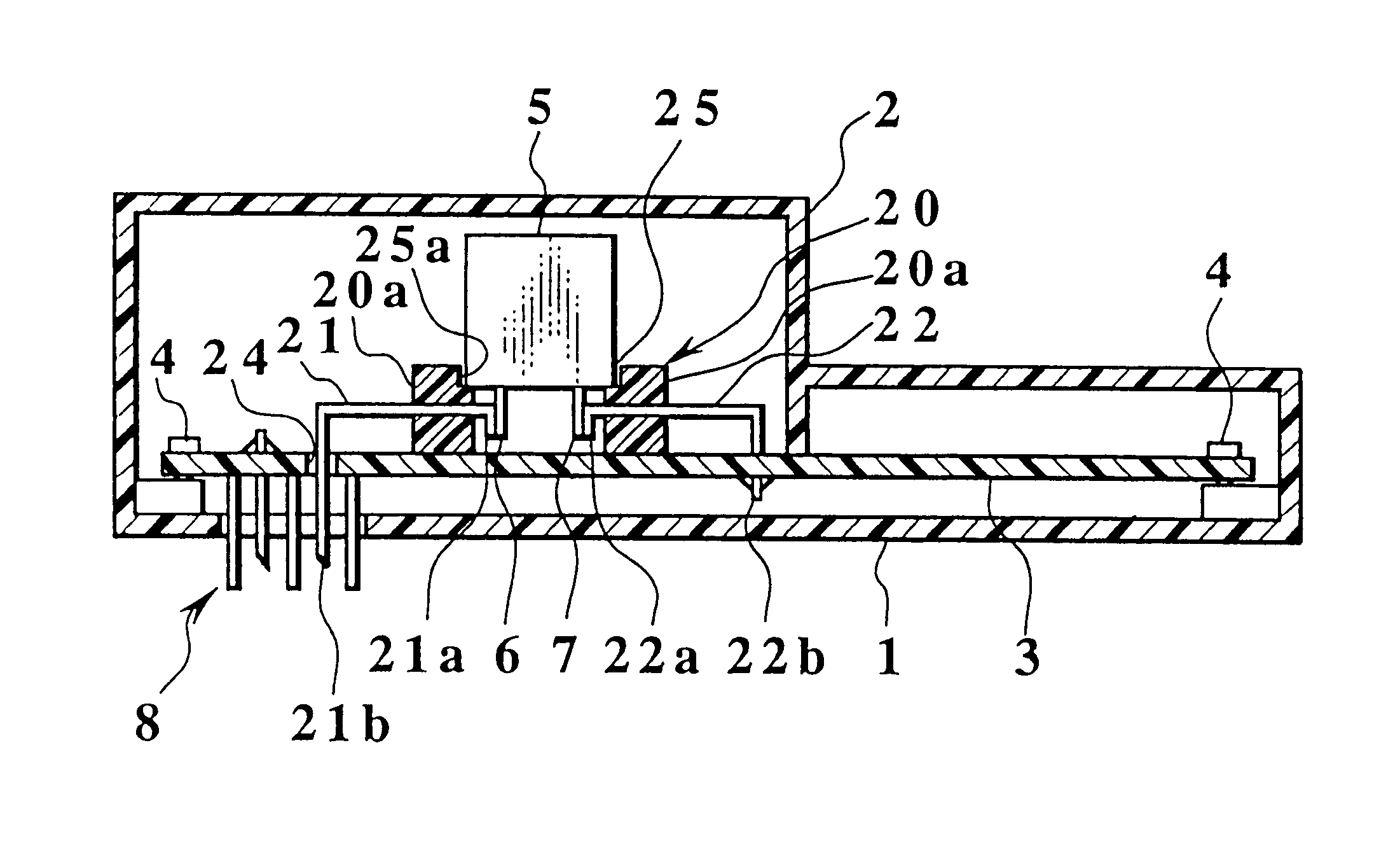
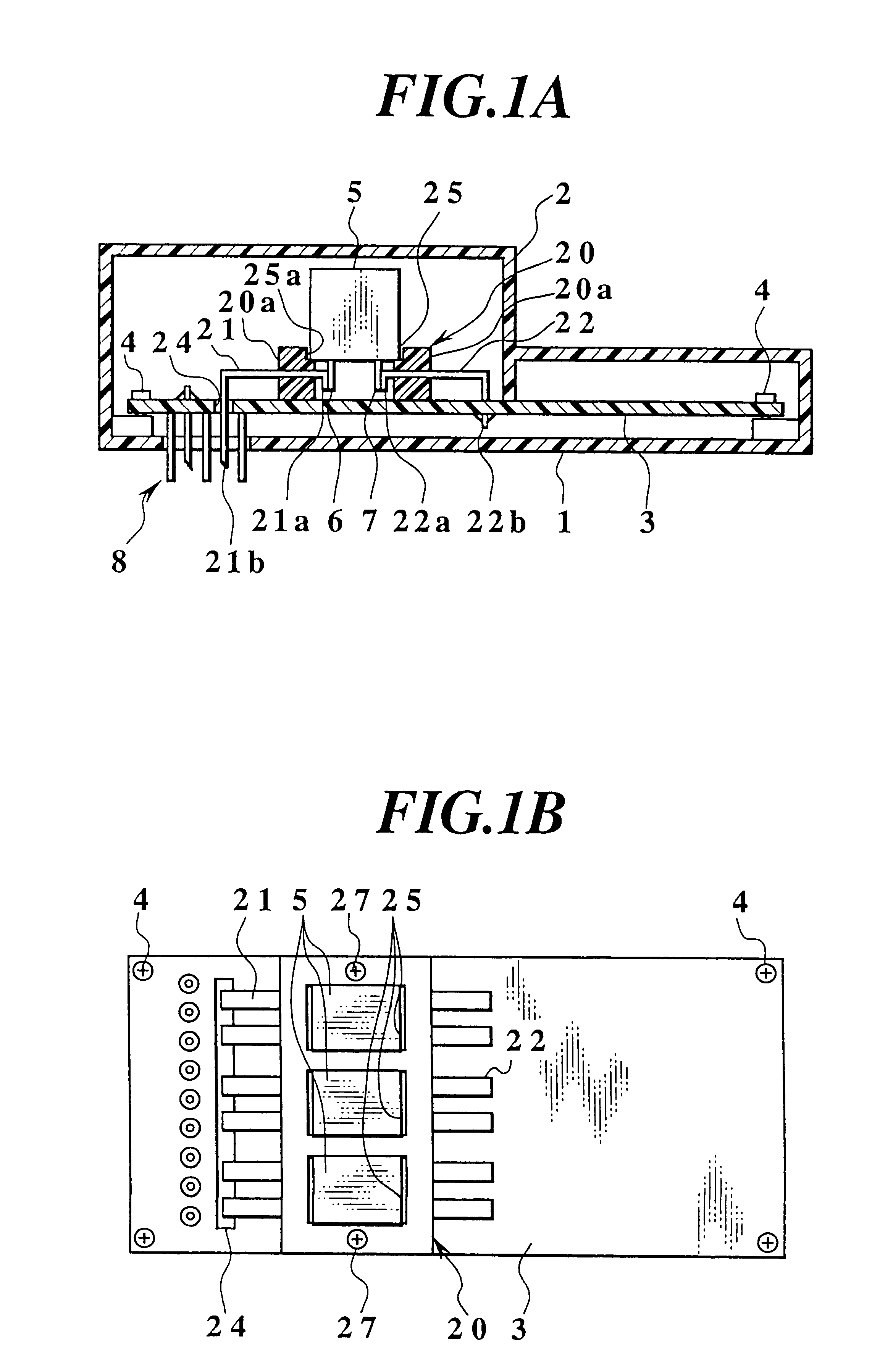
FIGS. 1A and 1B show an electric connection box to which a mounting structure according to the present invention is applied, FIG. 1A being a side cross-sectional view of the electric connection box, and FIG. 1B being a plan view showing a state in which a cover case of the electric connection box is removed. Also, FIGS. 2A and 2B are perspective views showing two bus bars which are taken out.

In these figures, a reference numeral 1 denotes a case body, 2 denotes a cover case, 3 denotes a printed circuit board, and the printed circuit board 3 is fixed on the case body 1 by means of a screw 4. A relay 5 is mounted on the printed circuit board 3 via a resin block 20. The resin block 20 is formed by subjecting two kinds of a first bus bar 22 and a second bus bar 21 to insert molding, and is fixed on the printed circuit board 3 by means of a screw 27.

The resin block 20 has a rectangular parallelepiped shape, and is formed with relay mounting openings 25 which are arranged in line on the m...

second embodiment

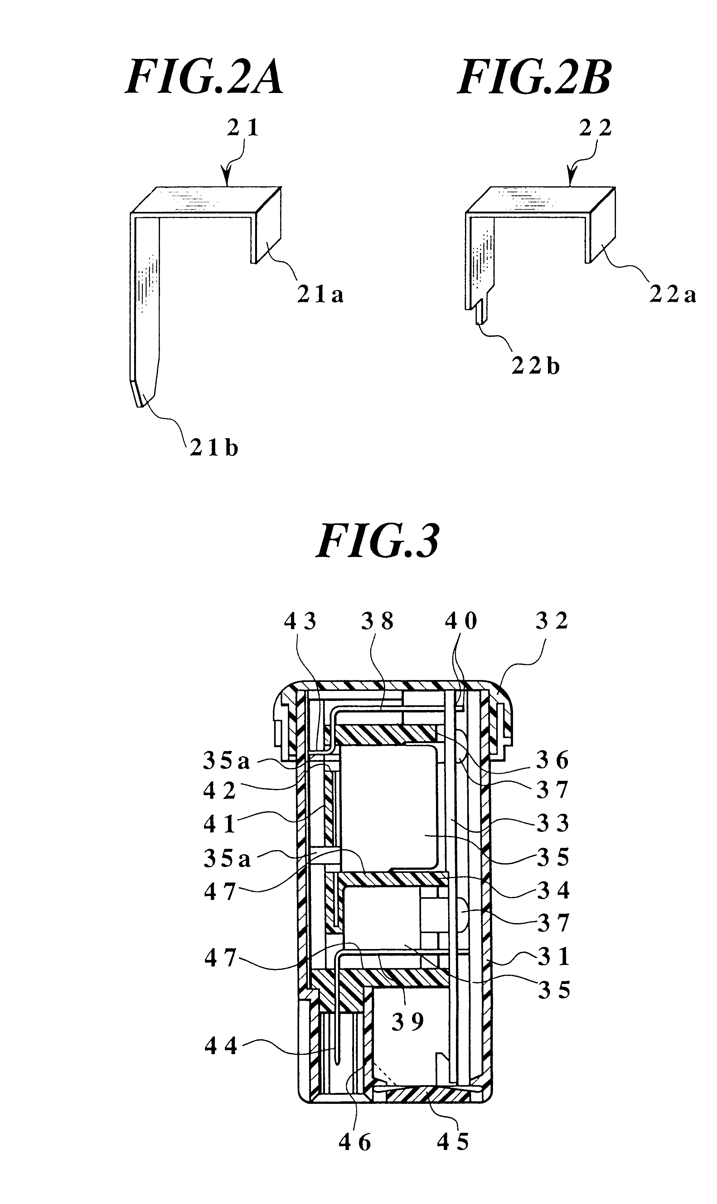
FIG. 3 and FIG. 4 show an electric connection box to which a mounting structure according to the present invention is applied, FIG. 3 being a cross-sectional view of the electric connection box, and FIG. 4 being an exploded perspective view thereof.

In FIG. 3 and FIG. 4, the electric connection box comprises a case body 31 having an upper opening, a cover case 32 which is capable of closing the upper opening of the case body 31, a printed circuit board 33 on which a printed wiring pattern or interconnecting pattern (not shown) is formed, a resin block 34 which is fixed onto the printed circuit board 33, and a relay 35 which is connected to the printed wiring pattern formed on the printed circuit board 33.

The resin block 34 has a rectangular parallelepiped shape, and has a fixing surface 36 which is fixed to the printed circuit board 33 at its one side. The fixing surface 36 side is fixed onto the printed circuit board 33 by means of a screw 37 so as to face the printed circuit board ...


PUM


Abstract

In a mounting structure for a relay arranged on a printed circuit board, a resin block having at least one insert-molded bus bar is fixed on the printed circuit board. One end of the bus bar held by the resin block is joined together with a terminal of the relay by welding, while the other end of the bus bar is soldered to a printed wiring pattern formed on the printed circuit board. Therefore, a heat (temperature) of the terminal of the relay can be absorbed through the bus bar and the resin block.

Description

1. Field of the InventionThe present invention relates to a mounting structure for a relay which is mounted under a high temperature environment such as an engine room of an automobile.2. Description of the Related ArtIn general, when mounting a relay on a printed circuit board in an electric connection (junction) box of an automobile, a terminal of the relay is soldered thereon in an automatic process of a flow system.In the related art, the printed circuit board of the electric connection box is fixed onto a case body by means of a screw. A relay is mounted on the printed circuit board, and then, the terminal of the relay is soldered to a printed wiring pattern on the printed circuit board. Moreover, in order to make an electrical connection with the outside, a connector terminal constituting a connector is soldered onto the printed circuit board.In the case where the aforesaid electric connection box is mounted under a high temperature environment such as an engine room of an aut...

Claims


Application Information

Patent Timeline
Patent Type & Authority Patents(United States)
IPC IPC(8): H01H50/14H01H50/00H01H50/12H01H50/04H01H50/02H05K3/30H05K1/02H05K1/18H05K7/12
CPCH01H50/14H01H50/047H01H50/12H05K1/0263H05K1/18H05K3/301
Inventor KONDO, YOUICHISUZUKI, MASATAKAWATANABE, YASUYUKI
Owner YAZAKI CORP
Why Eureka
Try Eureka