Piezoelectric resonator, process for the fabrication thereof including its use as a sensor element for the determination of the concentration of a substance contained in a liquid and/or for the determination of the physical properties of the liquid

a technology of piezoelectric resonators and sensors, which is applied in piezoelectric/electrostrictive devices, testing metals, and testing fluids using sonic/ultrasonic/infrasonic waves. it can solve the problems that affect the resonance behavior of small plates 8 and the resonating behavior of the resonator may be impaired

Inactive Publication Date: 2001-03-06
FRAUNHOFER GESELLSCHAFT ZUR FOERDERUNG DER ANGEWANDTEN FORSCHUNG EV
View PDF23 Cites 144 Cited by
  • Summary
  • Abstract
  • Description
  • Claims
  • Application Information

AI Technical Summary

Problems solved by technology

However, due to the structure of the small plates, which can meanwhile be fabricated in a filigree manner, the resonating behavior of the resonator may be impaired, i.e. by mechanical tension in the small plates caused by the holding carriers or by contacting with electric lines.
What is disadvantageous in this setup, however, is that even with the least exerted force, which can act on the two parts 7 which are spaced apart, can generate mechanical tension in the small plate 8 glued between parts 7, thereby influencing the resonance behavior of small plate 8.
However, the use of conductive adhesives has the consequence that the electric contact cannot be disconnected, which, for instance, makes replacing the small oscillator quartz plate impossible or at least requires great manual skill.
The small oscillator quartz plates are glued or clamped in a holding means, which can impair the resonance behavior of the resonator itself due to mechanical tensions.
Moreover, glued and clamped electric contacts on the surface of small oscillator quartz plates are not totally reliable, in particular, when employed for measuring concentrations of substances in liquids.
A stable and uniform quality of the contacting is not possible by this means.
The integration of the piezoelectric resonator in a casing with respective electric contacting is difficult and time consuming.
For flow-through cells of this type, the user needs much time and manual skill in replacing the cell.
The work involved in this replacing hinders wide commercial acceptance of piezoelectric resonators.
By providing concrete contact structures in the electrode and counter electrode areas, component specific deviations, which may effect eventual measuring results can be considerably limited.

Method used


Image

  • Piezoelectric resonator, process for the fabrication thereof including its use as a sensor element for the determination of the concentration of a substance contained in a liquid and/or for the determination of the physical properties of the liquid
  • Piezoelectric resonator, process for the fabrication thereof including its use as a sensor element for the determination of the concentration of a substance contained in a liquid and/or for the determination of the physical properties of the liquid
  • Piezoelectric resonator, process for the fabrication thereof including its use as a sensor element for the determination of the concentration of a substance contained in a liquid and/or for the determination of the physical properties of the liquid

Examples


Embodiment Construction

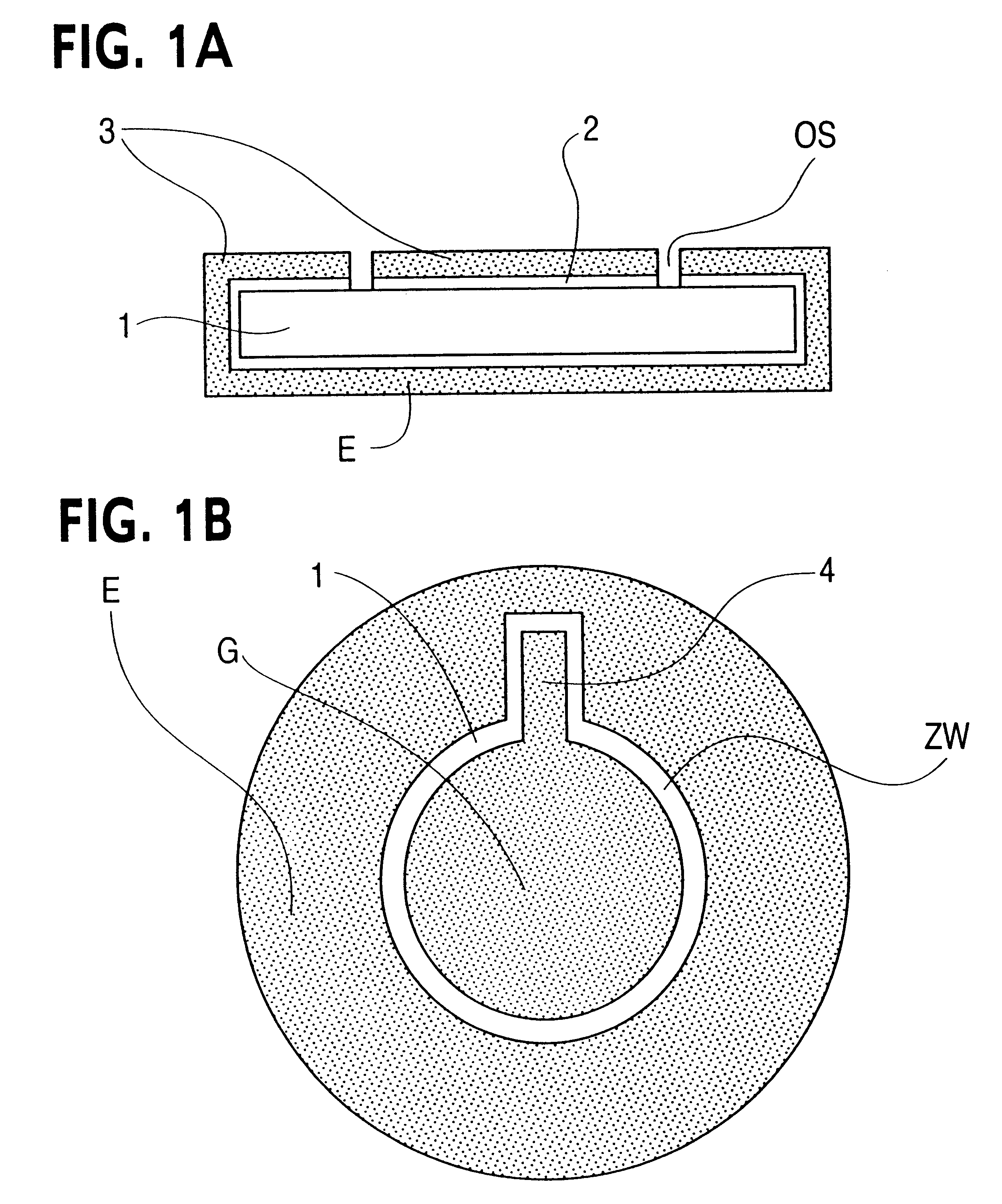
FIG. 1 shows in the upper part, a cross section of a coated piezoelectric resonator, whose core comprises a quartz substrate 1. According to FIG. 1 upper part, quartz substrate 1 designed as small oscillator quartz plate is nearly completely covered with an adhesive layer 2 with exception of the two let-open sites OS. Adhesive layer 2 comprises a titanium wolfram alloy and furthermore is coated with an electrically conductive layer 3, which preferably is of gold.

In the preferred embodiment according to FIG. 1, the entire lower side of the piezoelectric resonator is coated with a gold layer, which simultaneously also defines the electrode area E. Electrode area E extends over the edges of the piezoelectric resonator onto the upper side of the quartz substrate 1 on which, in addition, a counter electrode area G is precipitated, which is spaced a distance from electrode area E and thus is electrically insulated therefrom. An advantageous plane arrangement of electrode area E and counte...


PUM

PropertyMeasurementUnit
thicknessaaaaaaaaaa
thicknessaaaaaaaaaa
thicknessaaaaaaaaaa

Abstract

Disclosed is a piezoelectric resonator, a process for the fabrication thereof and its use as a sensor element, which implemented in a through-flow cell, is integratable in a measurement system for the determination of the concentration of a substance contained in a liquid and/or for the determination of the physical properties of the liquid. The piezoelectric resonator is designed plane and is provided on its surface with electric contact areas for an electrode and a counter electrode, which is connectable to a signal source as well as to a measurement device. For measuring, the piezoelectric resonator is brought into contact with the to-be-examined liquid on one side, with the resonator responding to the accumulation of the mass of the to-be-detected substance or to a change in the physical properties of the liquid by changing its resonance frequency and/or oscillation amplitude.The present invention is distinguished by the fact that the piezoelectric resonator is provided with contact electrode areas which is contactable from one single side of the resonator. The resonator is the heart piece of a sensor element, which is integrated in a through-flow cell. The through-flow cell us insertable module-like in a measurement arrangement for determining the concentration of a substance contained in a liquid and/or determining the physical properties of the liquid.

Description

1. Field of the InventionThe present invention relates to a piezoelectric resonator, a process for the fabrication thereof, its use as a sensor element, which, implemented in a through-flow cell, is integrable in a measurement system for the determination of the concentration of a substance contained in a liquid and / or for the determination of the physical properties of the liquid. The piezoelectric resonator is designed plane and is provided, on its surface, with electric contact areas for electrodes and counter electrodes, which is connectable to a signal source as well as to a measurement device. For measuring, the piezoelectric resonator is brought into contact with the to-be-examined liquid on one side, and the resonator responds to the accumulation of the mass of the to-be-detected substance or to a change in the physical properties of the liquid by altering its resonance frequency and / or oscillation amplitude.2. Description of the Prior ArtUsually, piezoelectric resonators ar...

Claims


Application Information

Patent Timeline
Patent Type & Authority Patents(United States)
IPC IPC(8): B06B1/06G01N29/02G01N27/00G01N29/22G01N29/036G01H13/00H03H3/02H03H3/00B06B1/02H03H9/19H03H9/00
CPCB06B1/0692G01H13/00G01N29/022G01N29/036G01N29/222H03H3/02H03H9/19B06B2201/71G01N2291/015G01N2291/0222G01N2291/0256G01N2291/02809G01N2291/0426
Inventor KOSSLINGER, CONRADUTTENTHALER, ERICHNITSCH, ANDREASHARLE, THOMAS
Owner FRAUNHOFER GESELLSCHAFT ZUR FOERDERUNG DER ANGEWANDTEN FORSCHUNG EV
Why Eureka
Try Eureka