Air Conditioning system and method for operating the same

a technology of air conditioning system and air conditioning system, which is applied in the field of air conditioning system, can solve the problems of abnormal condensation pressure of refrigerant, inability to exceed the cooling effect, and no benefit resulting from complex system, etc., and achieve the effect of superior dehumidification capability and performance characteristics

Inactive Publication Date: 2001-03-13
EBARA CORP
View PDF17 Cites 30 Cited by
  • Summary
  • Abstract
  • Description
  • Claims
  • Application Information

AI Technical Summary

Benefits of technology

Accordingly, by heating the refrigerant flowing into the compressor with post-desiccant regeneration air, so as to raise the temperature of the compressed superheated vapor of a refrigerant, i.e., its enthalpy of the vapor is increased, thereby increasing the proportion of the sensible heat in the heat discharged in a high-temperature heat source of a heat pump, and then the regeneration air is heated to increase the dehumidifying capability of a desiccant, thereby providing an energy conserving system with a superior dehumidifying capability. This process raises the regeneration temperature and increases the dehumidifying capability of the desiccant.
Accordingly, adsorption process and regeneration process of desiccant can be carried out continuously, and by selectively switching the flow direction of the refrigerant flowing in two low-temperature heat source heat exchangers for transferring heat with the process air and the regeneration air, heat can be obtained from either the process air or regeneration air, and an example of various modes of operation made possible by such a system is, by heating the refrigerant flowing into the compressor with post-desiccant regeneration air, so as to raise the temperature of the compressed superheated vapor of a refrigerant, i.e., its enthalpy of the vapor is increased, thereby increasing the proportion of the sensible heat in the heat discharged in a high-temperature heat source of a heat pump, and then the regeneration air is heated to increase the dehumidifying capability of a desiccant, and as an example of another mode of operation is, by changing the direction of flow of the refrigerant, dehumidifying operation only is possible when the sensible heat fraction is low, or the desiccant may be regenerated before starting the air conditioning system.
Accordingly, by selectively switching the flow direction of the refrigerant flowing in two low-temperature heat source heat exchangers for transferring heat with the process air and the regeneration air, heat can be obtained from either the process air or regeneration air, thereby enabling to perform an example of air conditioning such that, by heating the refrigerant flowing into the compressor with post-desiccant regeneration air, so as to raise the temperature of the compressed superheated vapor of a refrigerant, i.e., its enthalpy of the vapor is increased, thereby increasing the proportion of the sensible heat in the heat discharged in a high-temperature heat source of a heat pump, and then the regeneration air is heated to increase the dehumidifying capability of a desiccant.
Accordingly, without discharging process air that has not been sufficiently dehumidified when starting the system, heat can be obtained from regeneration air for desiccant regeneration while suppressing moisture adsorption by the desiccant, therefore, regeneration time is shortened to produce a desiccant-assisted air conditioning system having a good startup properties and pleasing performance.

Problems solved by technology

That is, cooling effect cannot exceed the capability of the heat pump (vapor compression cycle) used.
Therefore, there is no benefit resulting from making the system complex.
Therefore, to achieve this end objective, if the condensation temperature is increased to about 75.degree. C. in an effort to increase the regeneration temperature, in the resulting process, the condensation pressure of the refrigerant becomes abnormally high (24.1 kg / cm.sup.2) as shown by the dotted line in FIG. 11, and it is no longer possible to use HCFC22 compressor in designing a heat pump for use in a desiccant air conditioning system.

Method used


Image

  • Air Conditioning system and method for operating the same
  • Air Conditioning system and method for operating the same
  • Air Conditioning system and method for operating the same

Examples


first embodiment

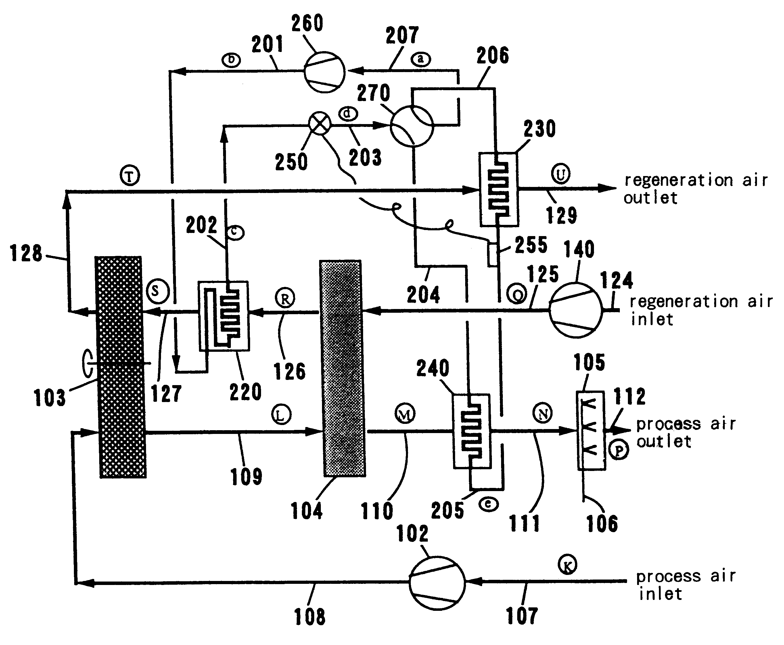
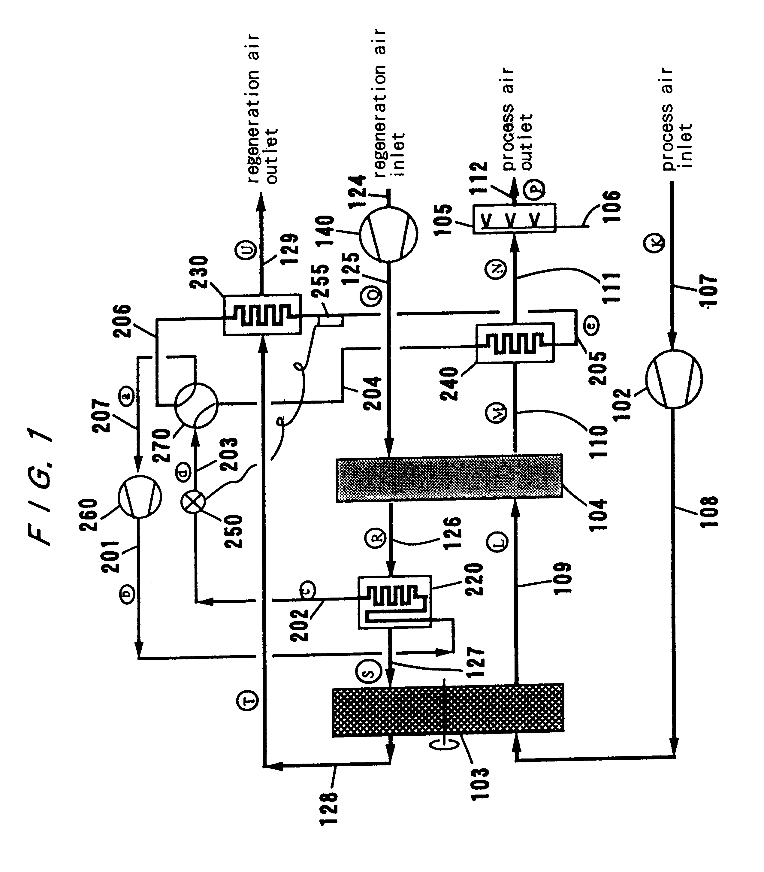
FIG. 1 shows a diagram of the basic structure of the air conditioning system of the present invention. A vapor compression type heat pump 200 comprises: a compressor 260; a first low-temperature heat source heat exchanger (evaporator) 240; a second low-temperature heat source heat exchanger (evaporator) 230; a high-temperature heat source heat exchanger (condenser) 220; and an expansion valve 250 so as to construct a vapor compression type refrigeration circuit. A four-way valve 270 is provided in a passage from an expansion valve 250 in this circuit to the compressor 260. The four-way valve 270 selectively switches the flow of the refrigerant heading towards the inlet of the compressor 260 between the two paths as follows. One path takes the refrigerant exiting the expansion valve 250 to four-way valve 270, a first low-temperature heat source heat exchanger (evaporator) 240, a second low-temperature heat source heat exchanger (evaporator) 230, and to a passage 207 to the inlet of t...

second embodiment

FIG. 6 shows this invention. This embodiment is similar to the first system, in which the vapor compression type refrigeration circuit of a heat pump 200 comprises: a compressor 260; a first low-temperature heat source heat exchanger (evaporator) 240; a second low-temperature heat source heat exchanger (evaporator) 230; a high-temperature heat source heat exchanger (condenser) 220; an expansion valve 250, and a four-way valve 270 is provided between a passage from the expansion valve 250 to the compressor 260 of the circuit, so that the four-way valve 270 can selectively switch the direction of the refrigerant flowing towards the inlet of the compressor 260 in such a way that the refrigerant exiting the expansion valve 250 passes from the four-way valve 270, to first low-temperature heat source heat exchanger (evaporator) 240, second low temperature heat source heat exchanger (evaporator) 230, and to a passage 207 to the inlet to the compressor via the other path of the four-way val...


PUM


Abstract

This invention provides an energy saving air conditioning system having an improved dehumidifying ability by raising the temperature or enthalpy of a compressed superheated vapor of a refrigerant for the heat pump, thereby to increase the proportion of the sensible heat in the heat discharged in a high-temperature heat source of the heat pump, and then increased enthalpy is used to heat regeneration air to improve the dehumidifying capability of the desiccant. The system includes a desiccant 103 for dehumidifying process air, a heat pump 200 having a compressor 260 for supplying heat to regeneration air for regenerating the desiccant, by utilizing process air as a low temperature source 240 and regeneration air as a high temperature source 220, and the system is operated so as to heat the refrigerant flowing into the compressor in the heat pump with regeneration air after it has regenerated the desiccant, so that the temperature of the compressed refrigerant flowing into the compressor will be increased, and then the gained heat is transferred to the regeneration air to increase its temperature before regenerating the desiccant.

Description

TECHNICAL FIELDThis invention relates to air conditioning systems, and relates in particular to an air conditioning system that can operate continually air dehumidifying process by a desiccant and regeneration of the desiccant by heat pump.BACKGROUND ARTFIG. 8 shows a system based on the conventional technology disclosed in a U.S. Pat. No. 4,430,864, which is comprised by: process air passage A; regeneration air passage B; two desiccant beds 103A, 103B; a heat pump 200 for regeneration of desiccant and cooling of process air. The heat pump 200 uses heat exchangers 220, 210 embedded in the desiccant beds 103A, 103B as high and low temperature heat sources respectively, in which one desiccant bed performs dehumidifying by passing process air, and the other desiccant bed performs regeneration of desiccant beds by passing regeneration air. After air conditioning is carried out for a specific time interval, four-way switching valves 105, 106 are operated to perform reverse processes in r...

Claims


Application Information

Patent Timeline
Patent Type & Authority Patents(United States)
IPC IPC(8): F24F5/00F25B13/00F25B29/00F24F3/00F24F3/14F28D21/00
CPCF24F3/1411F24F5/001F24F3/1423Y02B30/52F24F2003/144F24F2203/1016F24F2203/1028F24F2203/1032F24F2203/104F24F2203/1056F24F2203/1068F24F2203/1084F25B13/00F25B29/003F25B2313/02741
Inventor MAEDA, KENSAKU
Owner EBARA CORP
Why Eureka
Try Eureka