Apparatus and method for monitoring and reporting weather conditions

a weather condition and apparatus technology, applied in the field of improved methods and apparatus for monitoring and reporting weather conditions, can solve the problems of reducing visibility, limited human eye ability to see objects through the atmosphere, and general limited approach to sampling only small areas

Inactive Publication Date: 2001-03-27
CAMBRIDGE MANAGEMENT CORP
View PDF24 Cites 41 Cited by
  • Summary
  • Abstract
  • Description
  • Claims
  • Application Information

AI Technical Summary

Benefits of technology

Here it should be noted that the camera assigned for daylight surface and cloud cover observation and the IR camera may be used advantageously in combination for surveillance and cloud cover observation at all times, i.e. during daylight and conditions of reduced ambient light (e.g. nighttime). The images from the two cameras may be toggled back and forth in the simplest system. In another system, images from the two cameras may be combined at the pixel level, providing a generally uniform pictorial view of surface and / or cloud cover in all ambient light conditions.
In making visibility measurements, the platform is rotated to points whose separation depends upon the camera's angular field of view. For example, with a 15.degree. field of view, the platform stops every 15.degree.. Obviously, cameras with a field of view larger or smaller than 15.degree. can be used. At each point, a visibility range is determined for that sector and the data is stored. The reported visibility is in accordance with the Federal Meteorological Handbook (FMH) to "FAA Order 7900SA, Surface Weather Observing--METAR"; that is, the furthest distance at which known landmarks are visible around at least half the horizon. The stored information is updated with each rotation of the platform and a new visibility range calculated. A user interface allows the user to easily select and display weather data and cloud images for any selected sector and elevations above the horizon. The user may be close to the system but typically is at a remote location.
In one implementation, a distributed, networked set of semi-autonomous airfield data collection systems support database server sites, which collectively operate as a central depository for surface weather observation information. A typical airfield installation is composed of a sensor positioning unit with its installed sensors, a data collection and communications control computer, and an environmental management module. The airfield weather observation data and related imagery is transmitted electronically to remote users. The system offers the flexibility of processing the data and imagery at the airfield before transmission to the remote sites or processing after receipt of the data at the remote site. In all cases, the focus of the system is to deliver timely, accurate, and representative surface weather observation information of visibility, cloud height, cloud ceiling, cloud type, and amount of cloud cover. Users of the surface weather observation information and related imagery stored in the system may access it via computer workstations connected to the database servers by local area networks or remote communications links, including satellites and the Internet.

Problems solved by technology

The ability of the human eye to see objects through the atmosphere is limited by the presence of airborne particles, such as moisture, ice, sand, dust, and the like.
Both reflective loss and absorptive loss can cause a reduction in visibility.
This approach is generally limited to sampling only small areas and extrapolating a visibility report for a larger region on the basis of these samples.
These systems, however, often do not provide the current and accurate visibility and cloud height conditions that determine the arrival / departure envelope of a specific airport's active runway(s) especially during operationally significant weather changes.
The use of contract observers is costly, and their natural attrition requires continuous training of new observers--with associated delays in filling vacancies.
ASOS data is non-representative when weather is rapidly changing, which not only poses a problem in and of itself, but also creates a need for contract observers to compensate for this non-representative condition report.
Finally, the unique demands of remote airfields and their lack of timely information pose a severe problem for these locations.

Method used


Image

  • Apparatus and method for monitoring and reporting weather conditions
  • Apparatus and method for monitoring and reporting weather conditions
  • Apparatus and method for monitoring and reporting weather conditions

Examples


Embodiment Construction

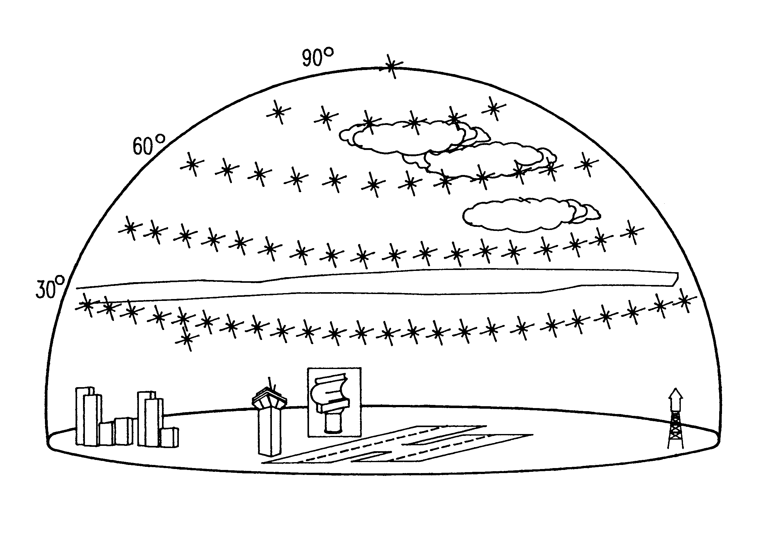
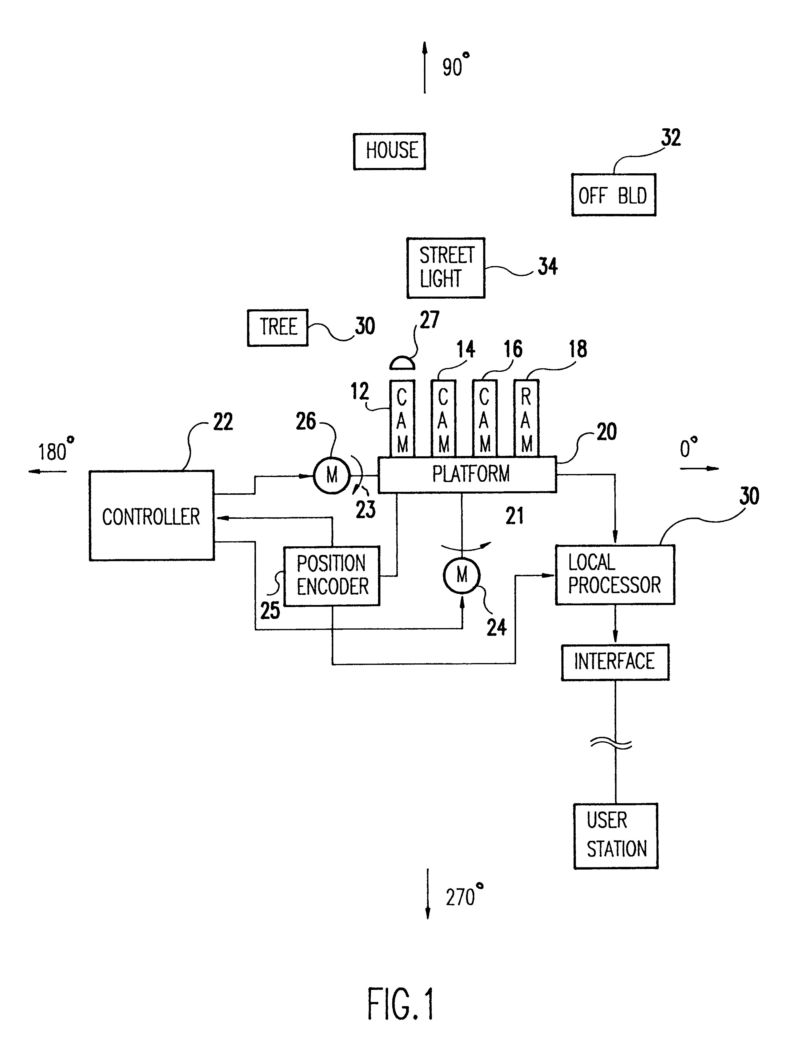
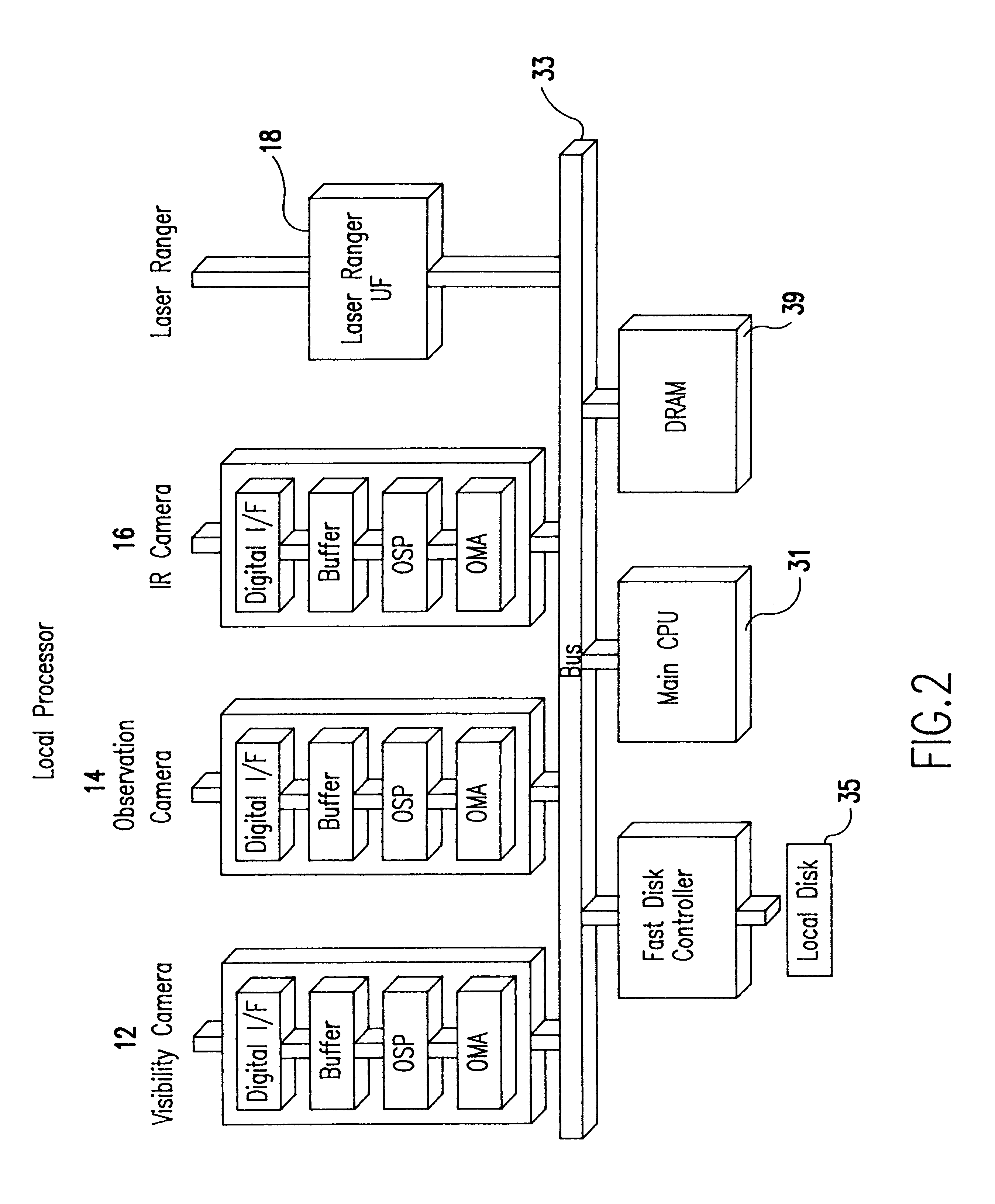
Referring now to FIGS. 1 and 2, in this preferred embodiment of the invention, a digital visibility camera 12, an observation camera 14, an infrared camera 16, and a laser range finder 18 are mounted on a platform 20, which is gimbal mounted for 360.degree. rotation about a vertical axis 21 and 90.degree. horizontal axis 23. The platform and its associated electronics are enclosed in a weather tight and environmentally controlled enclosure (not shown) with a window through which the cameras and laser range finder are pointed. A servo motor 24 rotates the platform about the vertical axis and a servo motor 26 rotates the platform about the horizontal axis 23. Preferably closed loop servo systems with platform position encoder 25 are used to precisely point the platform in a sequence of selected directions in response to inputs from a controller 22. Each camera, in this exemplary embodiment, has a field view or approximately 15.degree.. Obviously, cameras with larger or smaller fields ...


PUM


Abstract

A weather monitoring, measuring and reporting system which uses unattended, high-resolution digital cameras and laser rangers to both measure and display weather conditions in a local region, such as the region surrounding an airport. Visibility is estimated by processing images in the camera's field of view at known range distances. The light response of the camera is matched to the light response of the human eye. In a preferred embodiment of the invention, the camera generates a digital pixel image of range objects; that is, prominent terrain objects such as, buildings, water towers, etc. in the camera's field of view. The digital pixel values of these range objects are stored in system memory at known address locations. The contrast between an average background pixel value in a region adjacent to an object and the average object pixel value is used to determine if the object is visible. Objects in the field of view are sequentially examined until the contrast to an object falls below the established threshold at which point the visibility is reported as extending to the next closest object with a contrast above the threshold. If the contrast for all objects exceeds the threshold, the process stops and the visibility range is reported as unlimited.

Description

1. Field of the InventionThis invention relates to an improved method and apparatus for monitoring and reporting weather conditions in a defined region, for example, airport visibility and ceiling conditions. More particularly, it relates to a method and apparatus which provides accurate, representative, and timely condition and surveillance reports without the need for human intervention. This invention has particular application to the monitoring and reporting of airport weather, and will be explained in that context here. However it will be appreciated that the invention is generally applicable to monitoring and reporting visibility, cloud ceiling, and related weather conditions generally in a defined region.2. Description of the Prior ArtThe ability of the human eye to see objects through the atmosphere is limited by the presence of airborne particles, such as moisture, ice, sand, dust, and the like. Both reflective loss and absorptive loss can cause a reduction in visibility. R...

Claims


Application Information

Patent Timeline
Patent Type & Authority Patents(United States)
IPC IPC(8): G01W1/00G01W1/02G01S17/95G01S17/00G01S17/02G01S7/00G01S7/48G01S7/51G01S17/86
CPCG01S7/003G01S7/51G01S17/023G01S17/95G01W1/02G06K9/28G01S17/86Y02A90/10G06V30/144
Inventor DOERFEL, STEVE
Owner CAMBRIDGE MANAGEMENT CORP
Why Eureka
Try Eureka