Power capacitor

a technology of power capacitors and capacitors, applied in the direction of capacitors, basic electric elements, electric devices, etc., can solve the problems of small outer cooling surface of such capacitors, poor utilization of housing volume, and large space requirements of arrangement in which a plurality of such capacitors are arranged alongside one another

Inactive Publication Date: 2001-04-03
VISHAY ELECTRONICS
View PDF8 Cites 85 Cited by
  • Summary
  • Abstract
  • Description
  • Claims
  • Application Information

AI Technical Summary

Problems solved by technology

Power capacitors with circular, round housings have, among other things, the disadvantage that any arrangement in which a plurality of such capacitors are arranged alongside one another requires a relatively large amount of space.
Moreover, the outer cooling surface of such capacitors is relatively small.
However, it is a disadvantage of such capacitors that when using round coils, the housing volume is only poorly exploited.
In the known capacitors it is frequently also necessary for electrical connections of different potential to cross one another, which is, as a rule, associated with a relatively high insulating cost and complexity for the associated wiring.
Moreover, the construction of electrical delta circuits always leads, both with round coils arranged above one another alongside one another and also with concentric round coils, to dissimilar, asymmetric line lengths with crossing lines of high potential difference, which, among other things, gives rise to the disadvantage of non-symmetrical series resistances and inductivities, and also to the danger of insulation faults.
In connection with star circuits With round windings accommodated above one another in cylindrical housings, a relatively high level of cost and complexity for insulation for the lines is generally necessary and much space is required in order to form the star point and to lead the phase lines upwardly to the common connection.
These additionally required measures are, however, always associated with an increased space requirement, a higher thermal resistance and higher additional costs.

Method used


Image

  • Power capacitor
  • Power capacitor
  • Power capacitor

Examples


Embodiment Construction

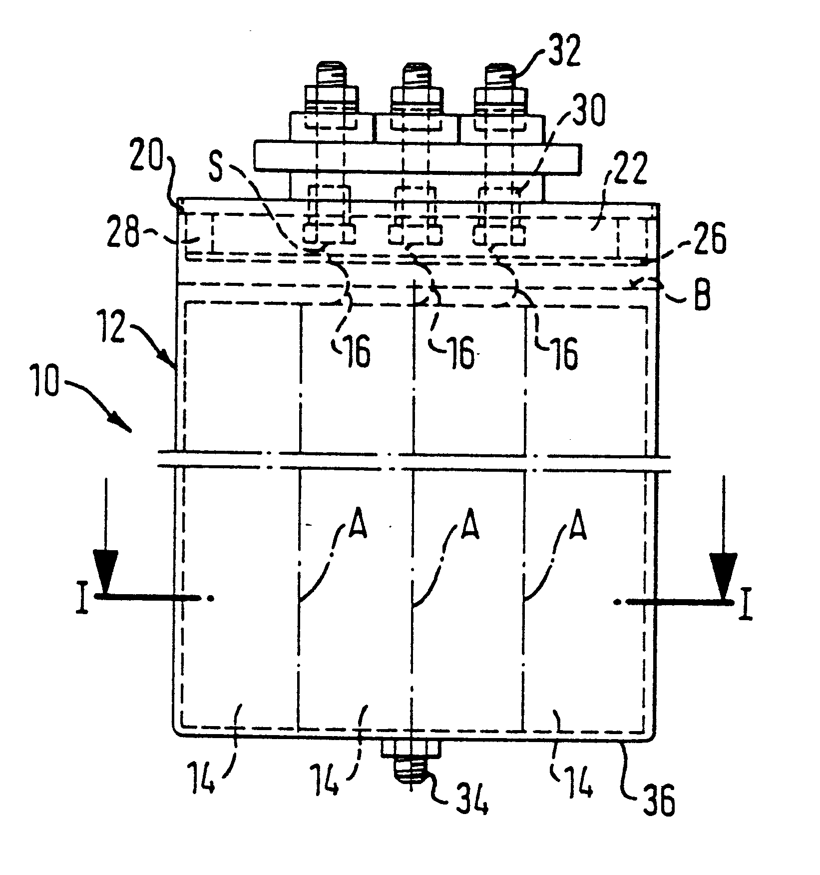
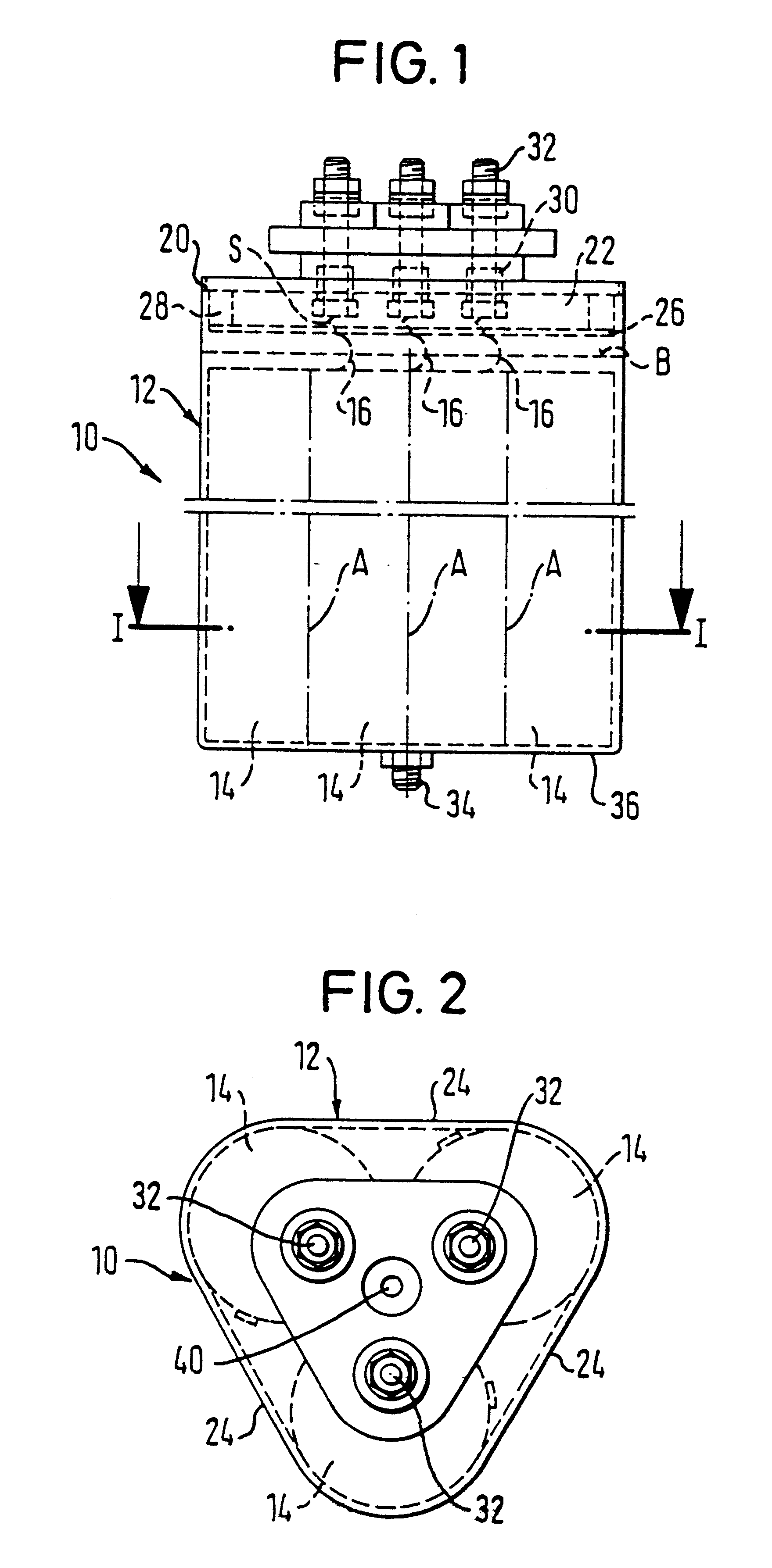
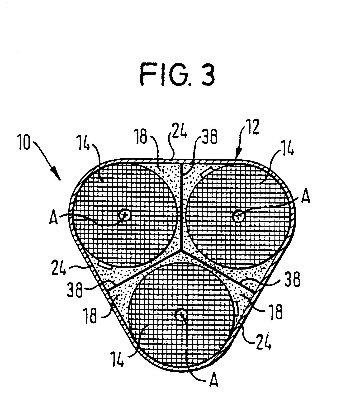
In FIGS. 1 to 3, an electrical power capacitor 10 having three round, wound elements 14 accommodated in a common housing 12 is shown in a purely schematic representation.

In this arrangement the three round, wound elements 14 are arranged in star-like manner alongside one another, with their axes parallel to one another. The housing 12 has in cross-section generally the shape of a triangle, the corners of which are rounded and have a radius of curvature corresponding at least substantially to the radius of the round, wound elements 14.

In the present case, the three wound elements 14 have the same diameter, so that the housing 12 generally has the shape of an equilateral triangle in cross-section.

The housing, which preferably consists of flow-pressed aluminum, is formed as a closed housing 12. It can be filled at least partly with potting material, oil and / or gas. In FIG. 1 the level for the potting material or for the oil filling is designated by B.

In the present case a filling of po...


PUM


Abstract

In a power capacitor with a plurality of round, wound elements accommodated in a common housing at least one wound element group consisting of three round, wound elements is accommodated in the housing, with the wound elements of the group being arranged in star-form alongside one another, with their axes parallel to one another. The housing has in cross-section in general the shape of a triangle having rounded corners, with a radius of curvature which corresponds at least substantially to the radius of the round, wound elements.

Description

1. Field of the InventionThe invention relates to a power capacitor comprising a plurality of round, wound elements accommodated in a common housing.2. Description of the Prior ArtThe previously customary power capacitors of this kind have, as a rule, a housing of round, circular cross-section or rectangular cross-section. Power capacitors with circular, round housings have, among other things, the disadvantage that any arrangement in which a plurality of such capacitors are arranged alongside one another requires a relatively large amount of space. Moreover, the outer cooling surface of such capacitors is relatively small. Capacitors with housings with a rectangular or square cross-section can admittedly be better placed together in a row. However, it is a disadvantage of such capacitors that when using round coils, the housing volume is only poorly exploited. In the known capacitors it is frequently also necessary for electrical connections of different potential to cross one anot...

Claims


Application Information

Patent Timeline
Patent Type & Authority Patents(United States)
IPC IPC(8): H01G4/38H01G2/10
CPCH01G4/38
Inventor HUBER, ROBERT
Owner VISHAY ELECTRONICS
Why Eureka
Try Eureka