Process for evaluating performance deterioration of a nitrogen oxide storage catalyst

a technology of nitrogen oxide storage catalyst and performance deterioration, which is applied in the direction of electrical control, exhaust treatment electric control, separation process, etc., can solve the problems of evaluating the performance deterioration of the catalyst used, damage to the storage function, and damage to the nitrogen oxide storage capacity of the catalys

Inactive Publication Date: 2001-04-17
UMICORE AG & CO KG +1
View PDF17 Cites 37 Cited by
  • Summary
  • Abstract
  • Description
  • Claims
  • Application Information

AI Technical Summary

Problems solved by technology

Since the storage capacity of a storage catalyst is limited, it has to be regenerated from time to time.
An important problem with modern exhaust gas treatment process is evaluating performance deterioration of the catalysts used in order to facilitate exchanging catalysts which are not working properly anymore.
This also applies to nitrogen oxide storage catalysts, the nitrogen oxide storage capacity of which can be damaged on the one hand by sulfur present in the fuel and on the other hand by thermal stresses.
With bifunctional storage catalysts, in principle both storage functions can be damaged by poisoning and by thermal effects.
Since nitrogen oxides and oxygen are both oxidizing components, their effects cannot be clearly separated from each other, so wrong diagnoses may be made when checking the catalyst.
In addition, the reductive components in the exhaust gas are oxidized, by consumption of the stored oxygen.
In the event of greater enrichment, after rapid emptying of the nitrogen oxide storage components, there is a surplus of reductive components which cannot be converted rapidly enough by the stored oxygen.

Method used


Image

  • Process for evaluating performance deterioration of a nitrogen oxide storage catalyst
  • Process for evaluating performance deterioration of a nitrogen oxide storage catalyst
  • Process for evaluating performance deterioration of a nitrogen oxide storage catalyst

Examples


Embodiment Construction

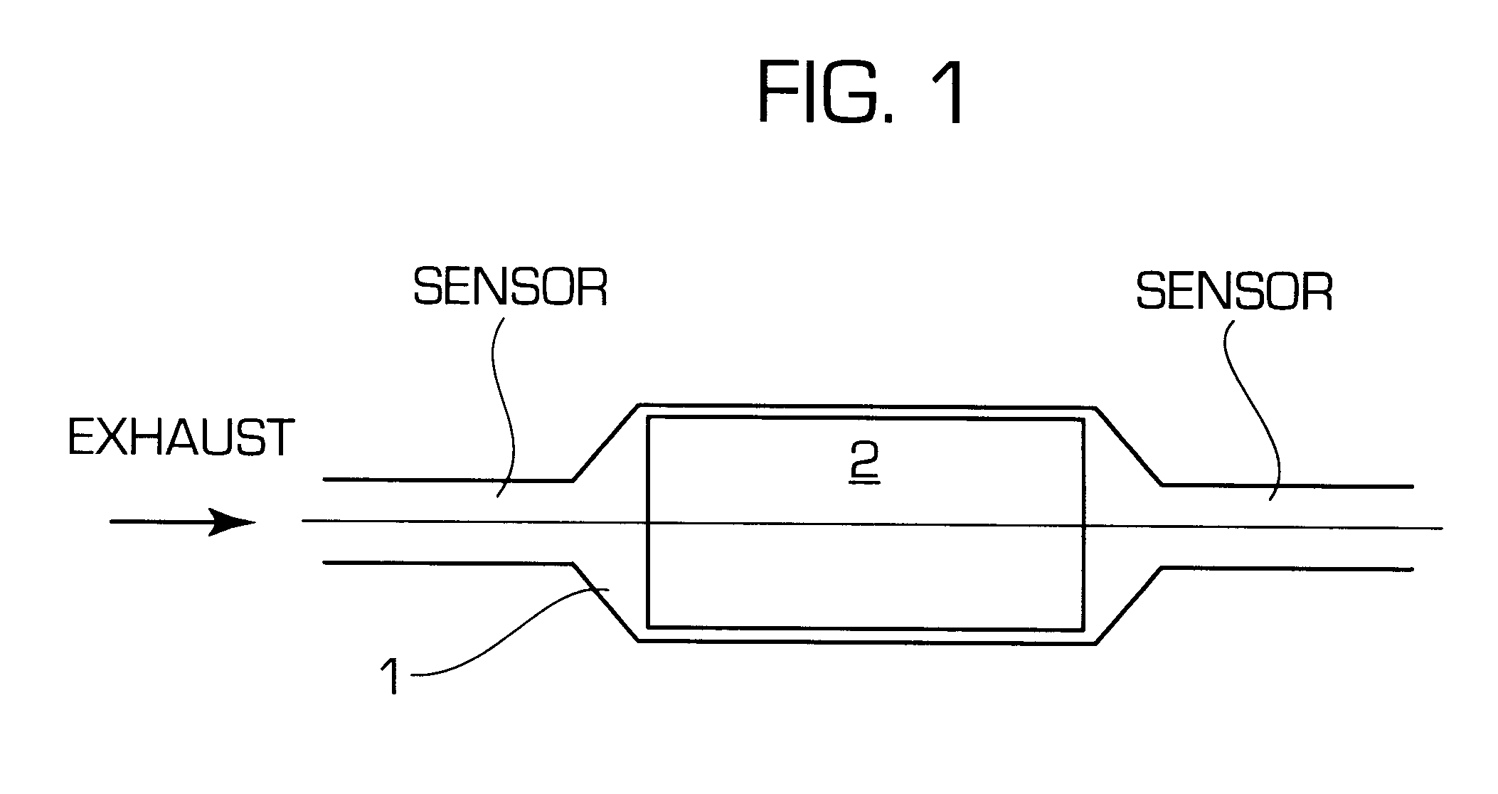
FIG. 1 schematically shows the layout of an exhaust gas treatment unit (1) such as is suitable for performing the process according to the invention. (2) designates the storage catalyst, the function of which it is intended to check regularly. This is built into a housing in the exhaust gas treatment unit. An oxygen sensor (sensor 1) is introduced into the exhaust gas pipe upstream of the catalyst, with respect to the direction of flow of the exhaust gas. Downstream of the nitrogen oxide storage catalyst is located a second oxygen sensor (sensor 2). In this example both sensors are two-point lambda sensors.

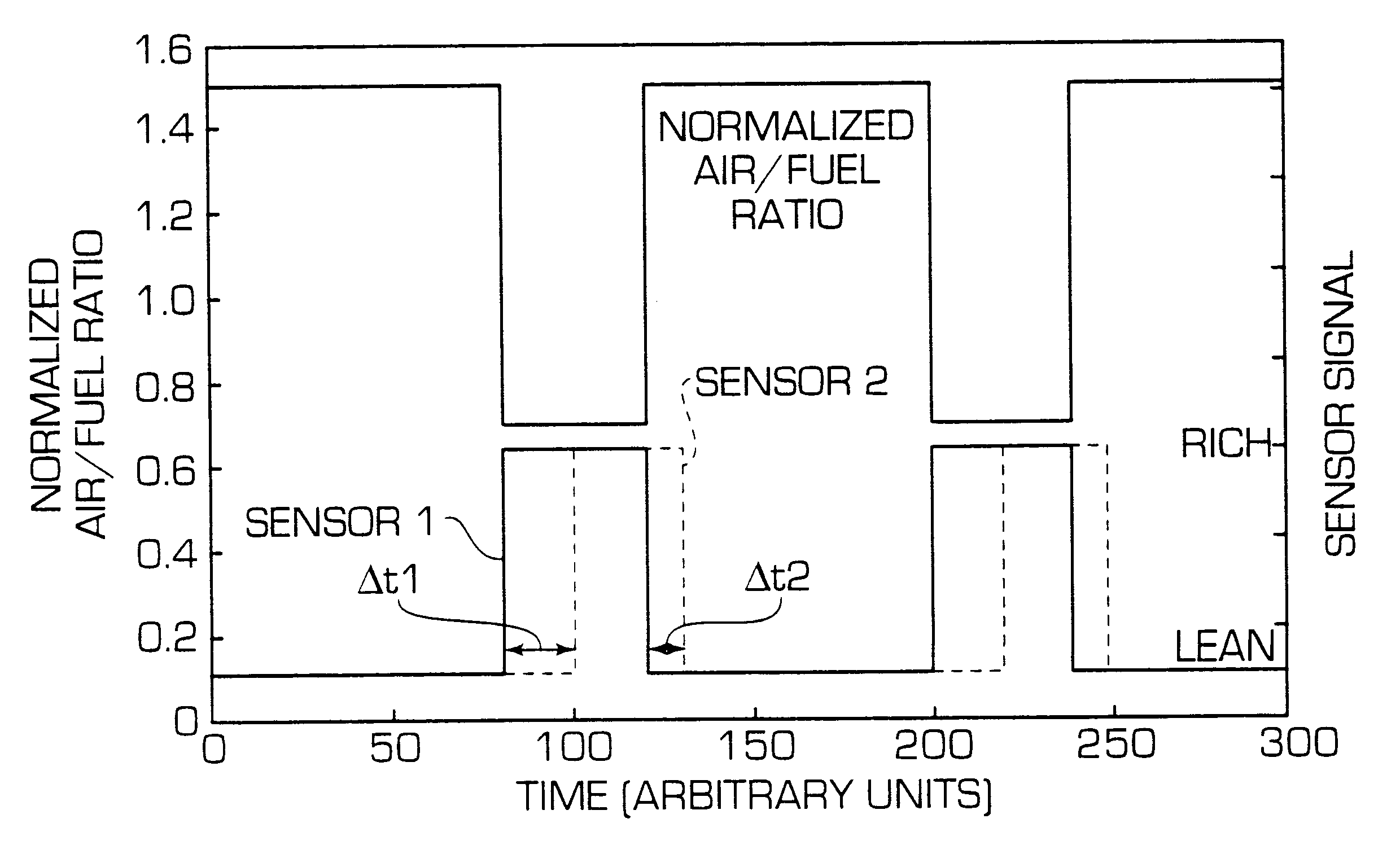
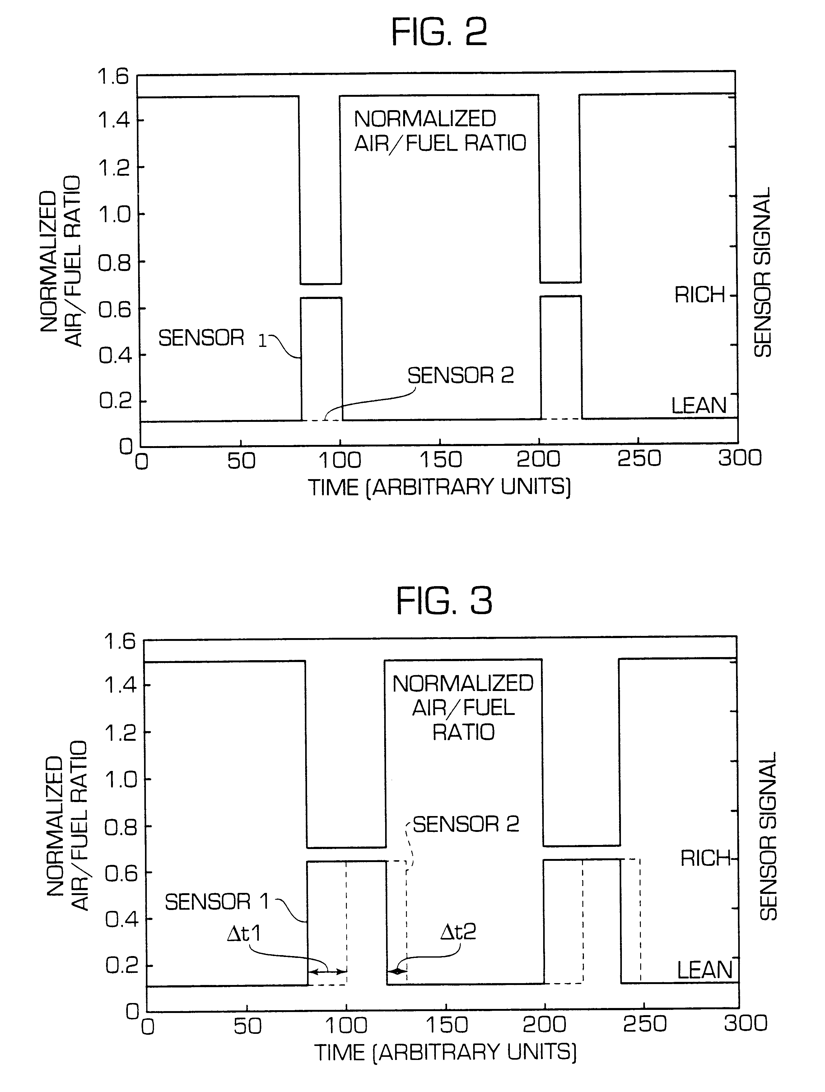
FIG. 2 shows the change in standardized air / fuel ratio imposed by the engine electronics system (not shown), upstream of the storage catalyst, and the signals from sensor 1 upstream of the catalyst and from sensor 2 downstream of the catalyst. The signal from sensor 1 follows the change in air / fuel ratio predetermined by the engine electronics system, while the signal from sensor ...


PUM


Abstract

A process for evaluating performance deterioration of a nitrogen oxide storage catalyst which has a nitrogen oxide storage function and an oxygen storage function and is operated with cyclic alternation of the air / fuel ratio in the exhaust gas from lean to rich. The nitrogen oxides are stored during the lean phase and the nitrogen oxides are desorbed and converted during the rich phase. To check the serviceability of the storage catalyst, the air / fuel ratio of the exhaust gas is switched from lean to rich and the rich phase is extended beyond the time required for complete desorption of the nitrogen oxides until at least the rich exhaust gas passes right through the catalyst and the time interval DELTAt1 produced between the first change-over until breakthrough of the rich exhaust gas and, after again switching from rich to lean running, the time interval DELTAt2 produced between the second change-over and passage of oxygen through the catalyst are measured and the time differences DELTAt1 and DELTAt2 are used for separate assessment of the oxygen storage function and the nitrogen oxide storage function of the catalyst.

Description

INTRODUCTION AND BACKGROUNDThe present invention relates to a process for evaluating performance deterioration of a nitrogen oxide storage catalyst which has a nitrogen oxide storage function and an oxygen storage function and is operated with cyclic alternation of the standardized air / fuel ratios in the exhaust gas from air / fuel ratios of greater than 1 (sorption phase) to store the nitrogen oxides to standardized air / fuel ratios of less than 1 (desorption phase) to desorb and convert the nitrogen oxides.Nitrogen oxide storage catalysts were developed specifically for the treatment of exhaust gases from lean operating internal combustion engines. Lean operating gasoline engines, so-called lean-burn engines and diesel engines belong to the group of lean operating internal combustion engines. Lean-burn engines, in particular with direct injection of gasoline, are being increasingly used in the vehicle construction sector since they enable theoretical fuel savings of up to 25% as comp...

Claims


Application Information

Patent Timeline
Patent Type & Authority Patents(United States)
IPC IPC(8): B01D53/94F01N3/08F01N3/20F01N3/24F01N3/28F01N9/00F01N11/00F02D41/04F02D41/14
CPCB01D53/9495F01N3/0814F01N3/0842F01N3/0864F01N11/007F02D41/0235F02D41/1441F01N3/0807F01N2550/03F01N2570/16F01N2900/0422F02D41/1456Y02T10/47F02D2200/0808F02D2200/0816Y02T10/40
Inventor STREHLAU, WOLFGANGMUSSMANN, LOTHARGOBEL, ULRICH
Owner UMICORE AG & CO KG
Why Eureka
Try Eureka