
Apparatus for drying granular objects involving pre-heating process

Inactive Publication Date: 2001-05-01
SATAKE CORP
View PDF12 Cites 26 Cited by
  • Summary
  • Abstract
  • Description
  • Claims
  • Application Information

AI Technical Summary

Benefits of technology

For drying the granular objects, as there is provided the heating process between the holding process and the drying process, the temperature from the center portion to the surface portion within the grain can be made uniform and, thus, distortion hardly occurs in the granular objects when they are exposed to the heated air for drying. As a result, not only it is possible to reduce damages of the granular objects caused by the drying, but also it is possible to make the drying more speedily. Further, since it is possible to introduce into the drying process, as a drying air, a heated air whose temperature has been lowered by mixing the outside air to the heated air forwarded from the heating process, even if the temperature of the heated air at the heating process is comparatively high, the heated air can be sufficiently lowered in its temperature by the introduction of the outside air to the extent that it is suitable for the drying operation. Further, the above heating process can be provided at the holding process, no additional space for installing the heating process is necessary, thereby realizing a compact size apparatus.
For the purpose of maintaining the temperature of the drying air at a predetermined one, there is provided means for detecting a temperature of the drying process and, for controlling, based on the detected temperature, the temperature of the heated air at the heating process. With this construction, when the heated air is converted to the drying air suitable for the drying with the outside air being taken-in, even if there occurs any changes in the external conditions such as the rising of the circumference temperature of the apparatus, which may cause the drying air temperature high otherwise, it is possible to keep the drying air to a stable temperature by the control of the temperature of the heated air itself.
In the heating process, a part of the heated air is introduced into the granular objects that are falling down, and the granular objects are exposed to the heated air. In this way, the raising of the temperature of the granular objects to an appropriate temperature is further accelerated, so that the temperature of the granular objects are raised from the starting stage of the drying and the drying speed is advanced. Further, since the heated air is applied to the granular objects at the heating process in addition at the drying process, the positive heating by the heating process in addition to the drying by the conventional drying process, the drying process consisting of the heating process and the drying process can be carried out with high efficiency. In this way, without enlarging the size of the drying apparatus, the drying efficiency is in substance elevated, thus meeting the demand and trend of a smaller sized apparatus.
The above explained drying process in which a part of the heated air is introduced into the flow of the flowing down granular objects includes an outside air adjusting means for increasing or decreasing the amount of in-taking outside air so that the amount of the heated air to be introduced into the granular objects may be changed. Specifically, when the amount of outside air is changed to be reduced by the adjustment of the outside air adjusting means, the amount of the shortage of the air corresponding to the decrease in the amount of the introduced outside air is compensated by the increase in the amount of a part of the heated air introduced into the granular objects in the heating process. This means that the amount of a part of the heated air introduced into the granular objects increases inversely with the decrease in the amount of introduced outside air. Because of this, the heated air introduced into the granular objects during the heating process increases and, accordingly, the temperature of the granular objects subjected to the heating process is raised faster. In order to carry out this more effectively, it is preferable that this process is performed only during the initial stage of the drying, for example, only during the period in which the granular object filled up are heated up through one cycle of all the processes from the heating process to the taking out process. By so doing, the temperature of the entire granular objects can be elevated more quickly to the temperature suitable for the fast drying and, thereafter, by starting the introduction of the outside air in an ordinary way or a steady state, it is possible to dry the entire granular objects more speedily.

Problems solved by technology

However, since the structure is such that the far infrared radiation generator should be installed within the drying chamber, the size of the apparatus inevitably became larger by the installation space of the far infrared radiation generator, and thus the apparatus itself unavoidably became large-sized.
That is, basically, in order to obtain the effects of radiant heat by providing the far infrared radiation generator within the drying apparatus, it is obvious that a correspondingly large space is required.
With use of a plurality of heat sources and need of controlling them separately, the apparatus will inevitably be costly.
As a result, it will be impossible to raise the temperature of the air at the heated air path chamber, which is to raise the temperature of grains by being in contact with the grains, to the extent sufficient to contribute to the pre-heating.

Method used


Image

  • Apparatus for drying granular objects involving pre-heating process
  • Apparatus for drying granular objects involving pre-heating process
  • Apparatus for drying granular objects involving pre-heating process

Examples


Embodiment Construction

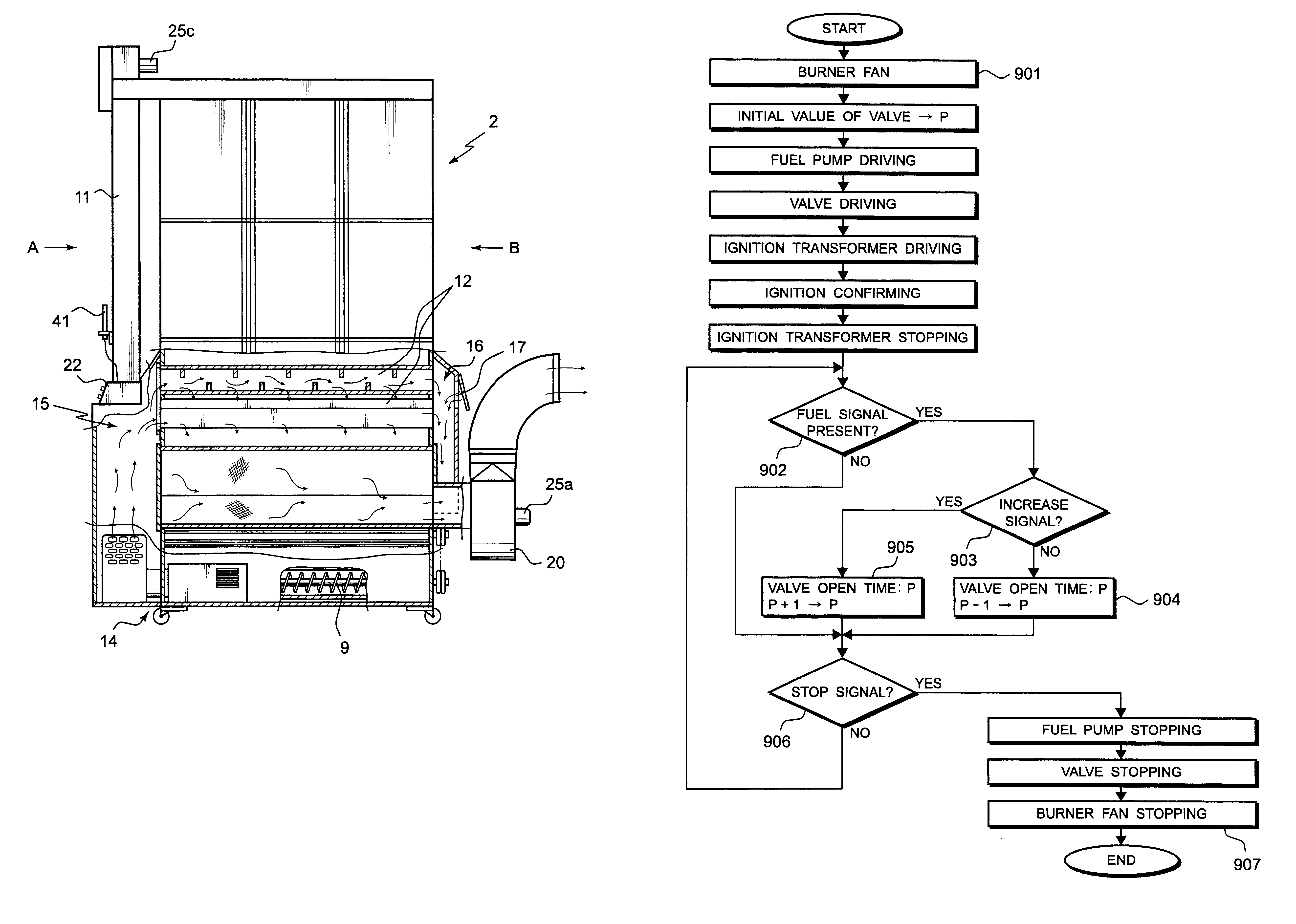
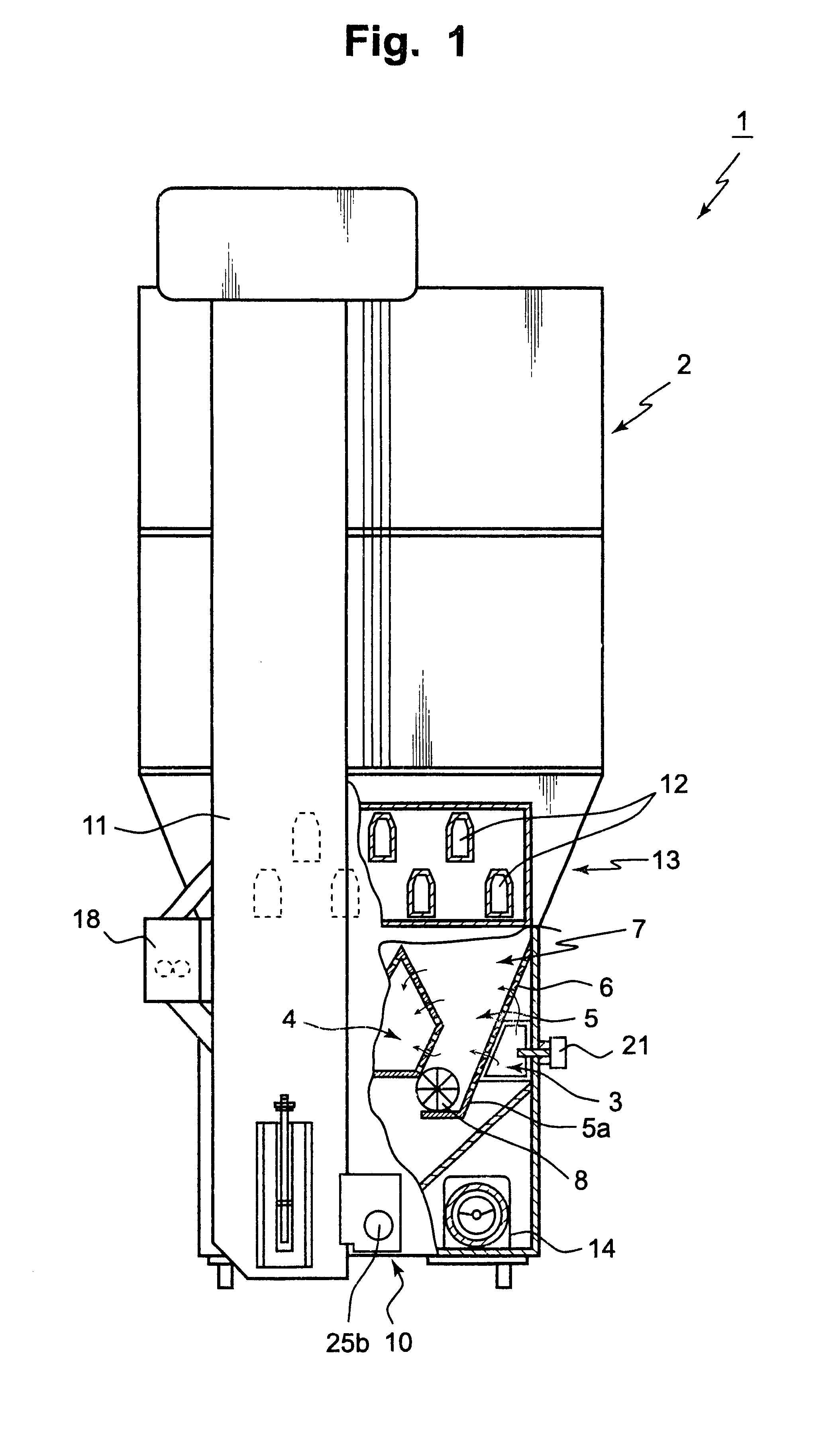
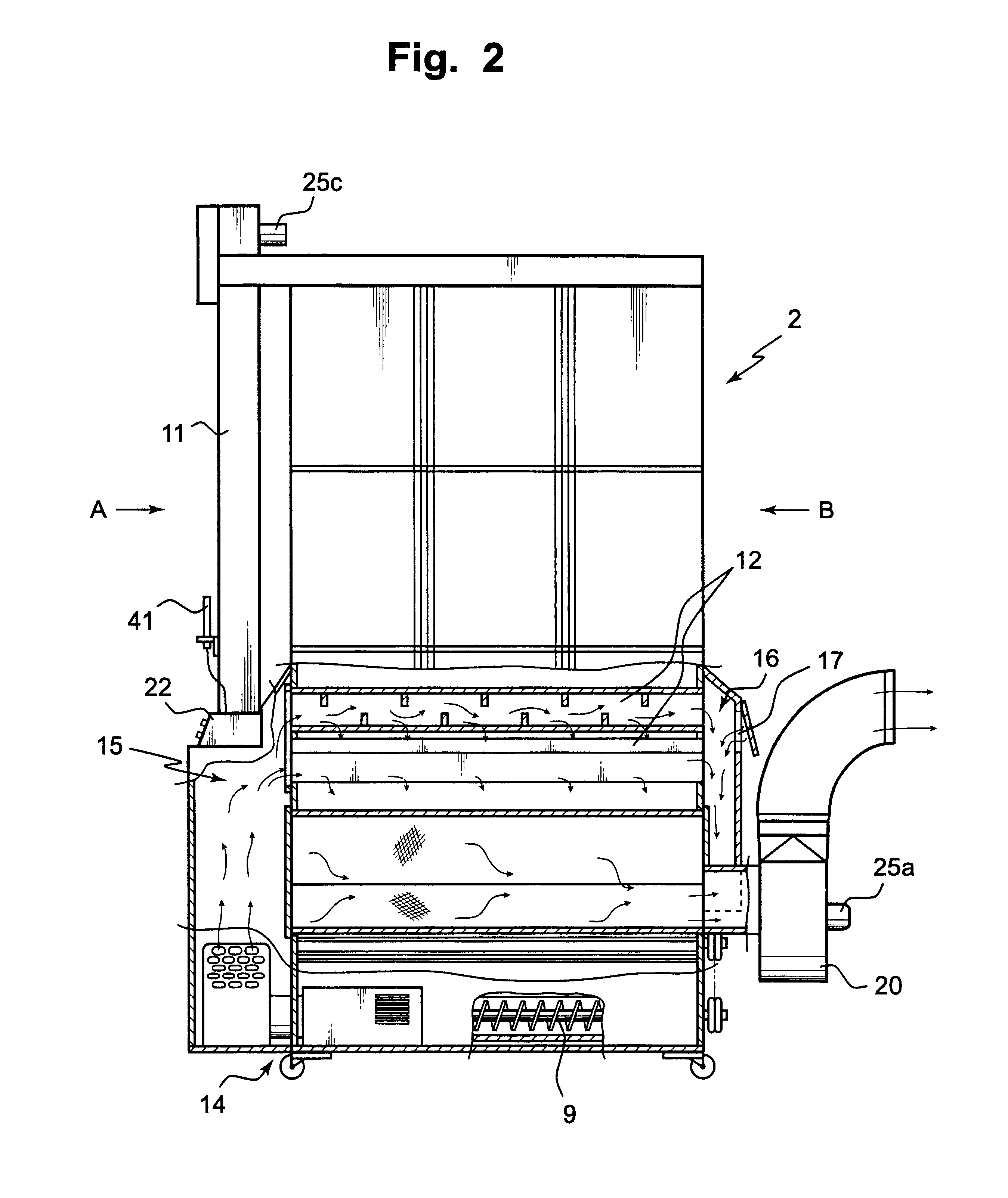
Now, a preferred embodiment of the invention is explained with reference to FIGS. 1 to 4. Here, the explanation is made on one example of a circulating type grain drying apparatus for drying grains as granular objects. A grain drying apparatus 1 is provided with, starting sequentially from the top thereof, a holding tank 2 for holding the grains to be subjected to the drying; a drying chamber 7 having air paths 3, an air exhaust path 4 and grain flow tubes 5 connected to the holding tank 2, which are divided by perforated plates 6 extending from a front side A to a rear side B; and a taking-out section 10 from which the dried grains are taken out thereat. The taking-out section 10 includes a rotary valve 8 for intermittently exhausting the grains flowing down on the non-porous slanted plates 5a connected to the perforated plates 6 of the drying chamber 7, and a screw-conveyor 9 for laterally feeding the grains fed from the rotary valve 8. Further, the taking-out section 10 and the h...


PUM


Abstract

An apparatus for drying granular objects comprises, from the top of the apparatus, a holding section; a heating section for heating the granular objects flowing down from the holding section, the heating section being provided beneath the holding section and having a plurality of air ducts to which heated air is introduced; a drying air producing section connected to the air ducts, in which the heated air from the air ducts is mixed with air taken-in from the outside of the apparatus to produce a drying air; and a drying section for drying the granular objects by directly exposing the granular objects to the drying air. The dried granular objects are taken out from a taking-out section and returned to the holding section through a bucket elevator. The apparatus further comprises a detector for detecting the temperature of the drying air. Based on the detected temperature, a control device controls the temperature of the heated air so as to keep the temperature of the drying air to a predetermined temperature. The temperature of the drying air can be set to a desirable temperature while the heated air for the heating is kept at a high temperature. The drying operation is performed speedily and safely.

Description

(1) Field of the InventionThe present invention relates to a method and an apparatus for drying granular objects in which the granular objects are dried by being exposed to drying air, and more particularly to a method and an apparatus for drying granular objects which utilize a structure for elevating the temperature of granular objects in advance to their exposure to the drying air.(2) Description of the Related ArtAs a conventional method for drying granular objects by exposing them to drying air, a common method was one in which a high temperature drying air was produced by a burner and a fan and the granular objects were repeatedly exposed to such drying air. However, for purposes of reducing the drying time and of preventing the quality change of the granular objects caused during the drying, a method involving pre-heating process of the granular objects, that is, a method with which the internal temperature of the granular objects is raised in advance before they are exposed ...

Claims


Application Information

Patent Timeline
IPC IPC(8): F26B17/12F26B21/10F26B9/06F26B17/16F26B9/08F26B21/06F26B17/14F26B1/00F26B3/00F26B23/10
CPCF26B9/087F26B17/122F26B17/16F26B21/10F26B3/00
Inventor SATAKE, SATORULIU, HOU QINGKUNINOBU, MAKOTOORIHASHI, KEISUKE
Owner SATAKE CORP
Learn More