Shadow mask for color cathode-ray tube and method of manufacturing the same

a color cathode-ray tube and mask body technology, applied in the manufacture of photo-emissive cathodes, electric discharge tubes, magnetic deflection devices, etc., can solve the problems of deterioration in the color purity of displayed images, shadow masks are liable to be resonated (howling), and the curved surface portion of the shadow mask is liable to be deformed, so as to restrict the shift of electron beams and improve the holding strength of the mask body

Inactive Publication Date: 2001-05-01
KK TOSHIBA
View PDF7 Cites 5 Cited by
  • Summary
  • Abstract
  • Description
  • Claims
  • Application Information

AI Technical Summary

Benefits of technology

In accordance with the above method, the mask body is fixed to the mask frame in a state that an internal stress in a direction of making small the radius of curvature of the mask body remains in that region of the mask body which is vicinity of the long axis, so that the curved surface holding strength of the mask body can be improved. Whereby it is possible to greatly restrict a shift in electron beam landing resulting from deformation or resonance of the mask body, local doming or the like. Therefore, the present invention can manufacture a color cathode-ray tube which is capable of displaying an image having preferably color purity.

Problems solved by technology

As a result, if an external force such as impact or the like is applied to the color cathode-ray tube, the curved surface portion of the shadow mask is liable to be deformed.
Further, if a vibration is applied to the color cathode-ray tube, the shadow mask is liable to be resonated (howling).
This causes a deterioration in a color purity of a displayed image.
If the aforesaid doming occurs, in particular, the electron beams do not properly land at a predetermined phosphor layers on an intermediate area of the screen, causing a deterioration in a color purity, likewise above.
If the plate thickness of the shadow mask is thickened, however, not only it is difficult to form a electron beam passing apertures having a desired shape and dimension, but also a material cost increases.
According to this method, however, an extremely great tensile stress must be applied to the shadow mask; for this reason, an extremely strong frame for holding the shadow mask is required.
Consequently, with the color cathode-ray tube being large-sized, a weight of the frame is greatly increased.
However, the shadow mask as described above has a problem that the curved surface holding strength of the shadow mask is low at the portions which are close to the long axis of the shadow mask if the shadow mask is made a large scale accompanying with a large scale of a color cathode-ray tube.

Method used


Image

  • Shadow mask for color cathode-ray tube and method of manufacturing the same
  • Shadow mask for color cathode-ray tube and method of manufacturing the same
  • Shadow mask for color cathode-ray tube and method of manufacturing the same

Examples


Embodiment Construction

Referring now to the accompanying drawings, a color cathode-ray tube according to an embodiment of the present invention will be described in detail.

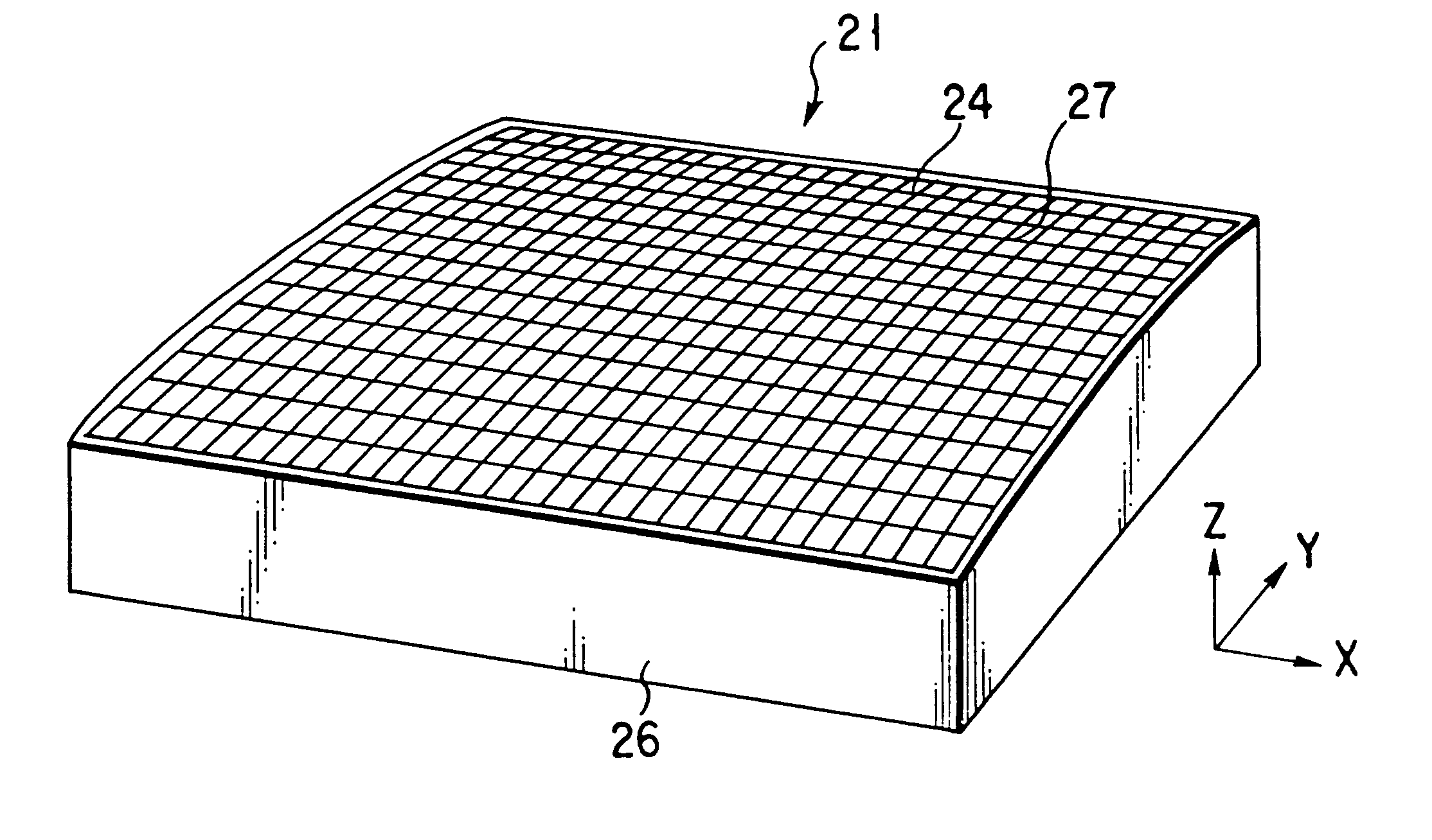
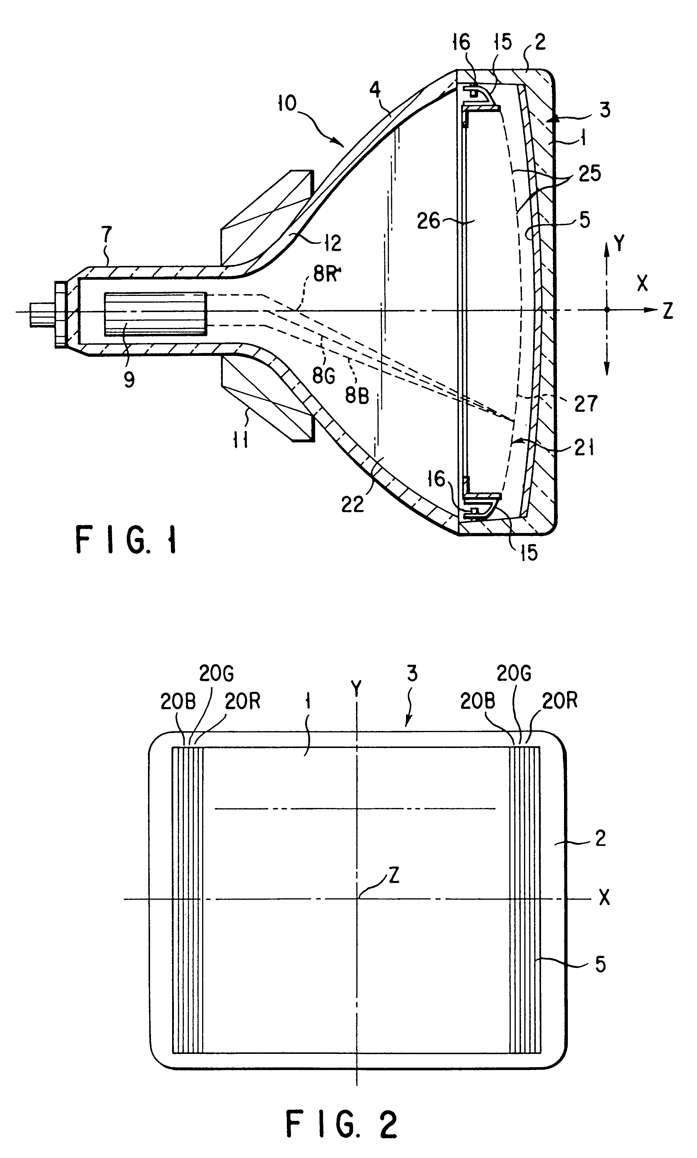
As shown in FIG. 1 and FIG. 2, there is shown a color cathode-ray tube. This color cathode-ray tube is a laterally long color cathode-ray tube which has a screen aspect ratio of 16:9, and includes a vacuum envelope 10 made of glass. The vacuum envelope 10 is formed of a face panel 3 which has a substantially rectangular effective portion 1 and a skirt portion 2 formed on the periphery of the effective portion 1, a funnel 4 joined to the skirt portion 2, and a cylindrical neck portion 7 extending from the funnel 4.

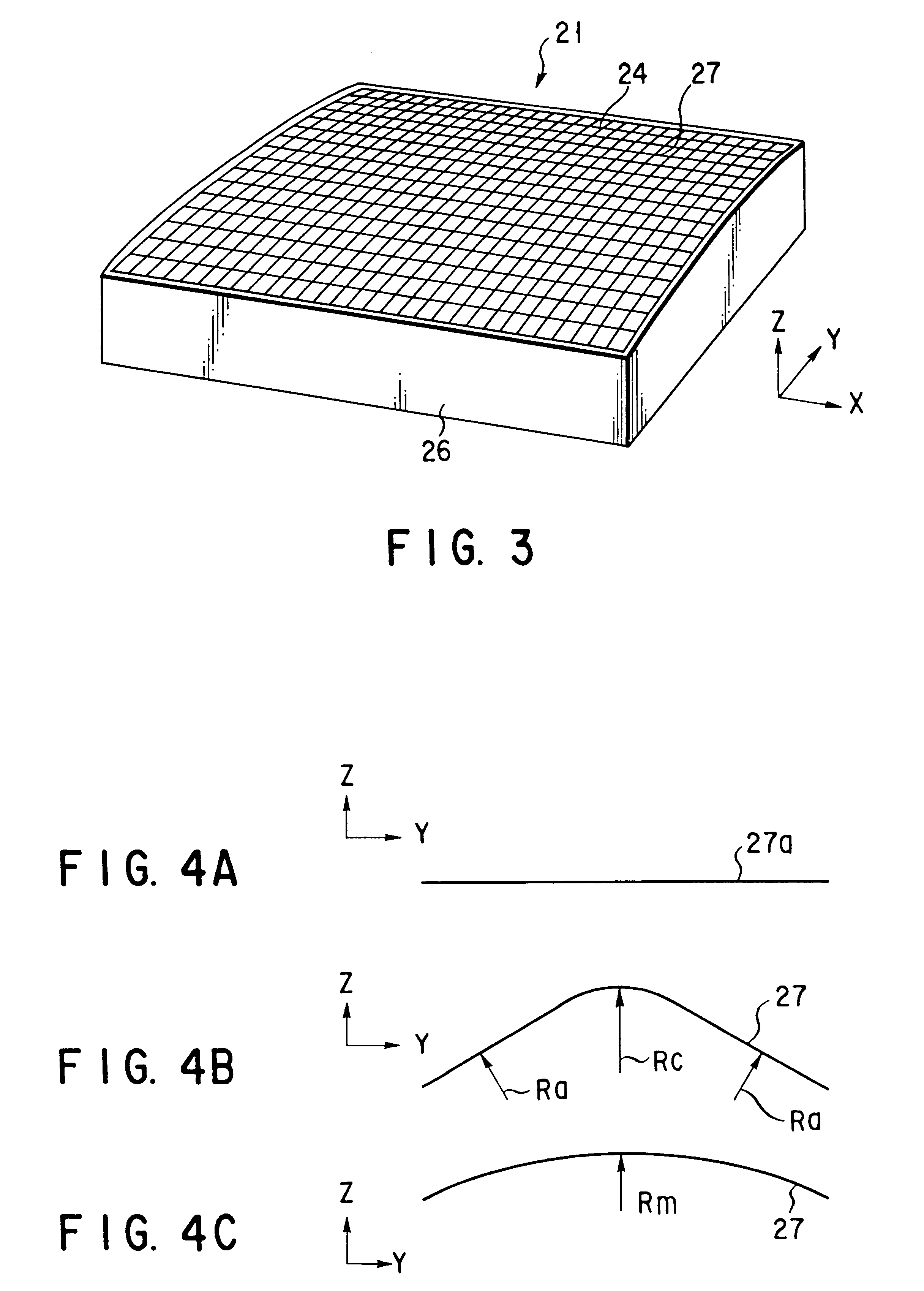
The effective portion 1 of the face panel 3 is formed into a substantially rectangular shape having a long axis (horizontal axis) X and a short axis (vertical axis) Y which pass through the tube axis Z of the cathode-ray tube and are perpendicular to each other. Further, an inner surface of the effective portion 1 is an aspheri...


PUM


Abstract

A shadow mask is arranged to face an inner surface of a substantially rectangular face panel. The shadow mask has a substantially rectangular mask body which has a number of apertures for passing an electron beam, and a rectangular mask frame which supports a peripheral edge portion of the mask body. The mask body is curved in a short axis direction, and is fixed to the mask frame in a state that an internal stress of a direction making small a radius of curvature of the short axis direction is applied. The shadow mask is manufactured in a manner that a rectangular flat mask is-plastically deformed so as to prepare the mask body having a curved surface such that a relation between a radius of curvature Rc of the short axis direction in the vicinity of the long axis and a radius of curvature Ra of the short axis direction in the vicinity of a long side becomes Rc<Ra, and thereafter, the mask body is fixed to the mask frame in a state of being elastically deformed in a direction in which a radius of curvature of the short axis direction becomes large.

Description

The present invention relates to a color cathode-ray tube including a shadow mask and a method of manufacturing the same.In general, a color cathode-ray tube includes a vacuum envelope which has a substantially rectangular face panel having a curved effective portion, and a funnel which has a cylindrical neck portion at its one end and is joined together with the face panel. Further, a substantially rectangular shadow mask is arranged on the inner side of the phosphor screen which is formed on the inner surface of the effective portion and includes three-color phosphor layers.An electron gun is arranged in the neck portion of the funnel. Three electron beams emitted from the electron gun are deflected by a magnetic field generated from a deflector (deflection yoke) mounted outside the funnel, and horizontally and vertically scan the phosphor screen through the shadow mask, and thereby displaying a color image.The shadow mask includes a substantially rectangular mask body which is fo...

Claims


Application Information

Patent Timeline
Patent Type & Authority Patents(United States)
IPC IPC(8): H01J29/07
CPCH01J29/07H01J2229/0744H01J2229/0788H01J2229/0794
Inventor NAKAGAWA, SHINICHIROOHAMA, SHINJISHIMIZU, NORIO
Owner KK TOSHIBA
Why Eureka
Try Eureka