
Use of biased high threshold voltage transistor to eliminate standby current in low voltage integrated circuits

Inactive Publication Date: 2001-05-01
GLOBALFOUNDRIES INC
View PDF5 Cites 47 Cited by
  • Summary
  • Abstract
  • Description
  • Claims
  • Application Information

AI Technical Summary

Benefits of technology

By way of introduction only, an integrated circuit in accordance with the present invention disconnects Vss or ground potential from the operating circuitry of the integrated circuit in the standby mode. Vss is received from off-chip and is supplied to the entire chip through a very large reduced-threshold voltage transistor. In the active mode, the well of the transistor is boosted by a predetermined voltage to lower the threshold voltage of the transistor for operation at low Vcc. In the standby mode, the gate and well of the transistor are grounded to the off-chip Vss, turning off the transistor and letting voltage of the operating circuitry float. This allows very quick turn on from standby to the active mode.

Problems solved by technology

These lower supply voltages create design and operation problems.
One problem is encountered when adapting conventional complementary metal-oxide-semiconductor (CMOS) circuits for low voltage operation.
However, transistors with low threshold voltages tend to have higher subthreshold current leakage.
In a large integrated circuit with thousands or millions of transistors, the total standby current would be too large for practical applications.
The large standby current would increase overall power consumption for the device to unacceptable levels.

Method used


Image

  • Use of biased high threshold voltage transistor to eliminate standby current in low voltage integrated circuits
  • Use of biased high threshold voltage transistor to eliminate standby current in low voltage integrated circuits
  • Use of biased high threshold voltage transistor to eliminate standby current in low voltage integrated circuits

Examples


Embodiment Construction

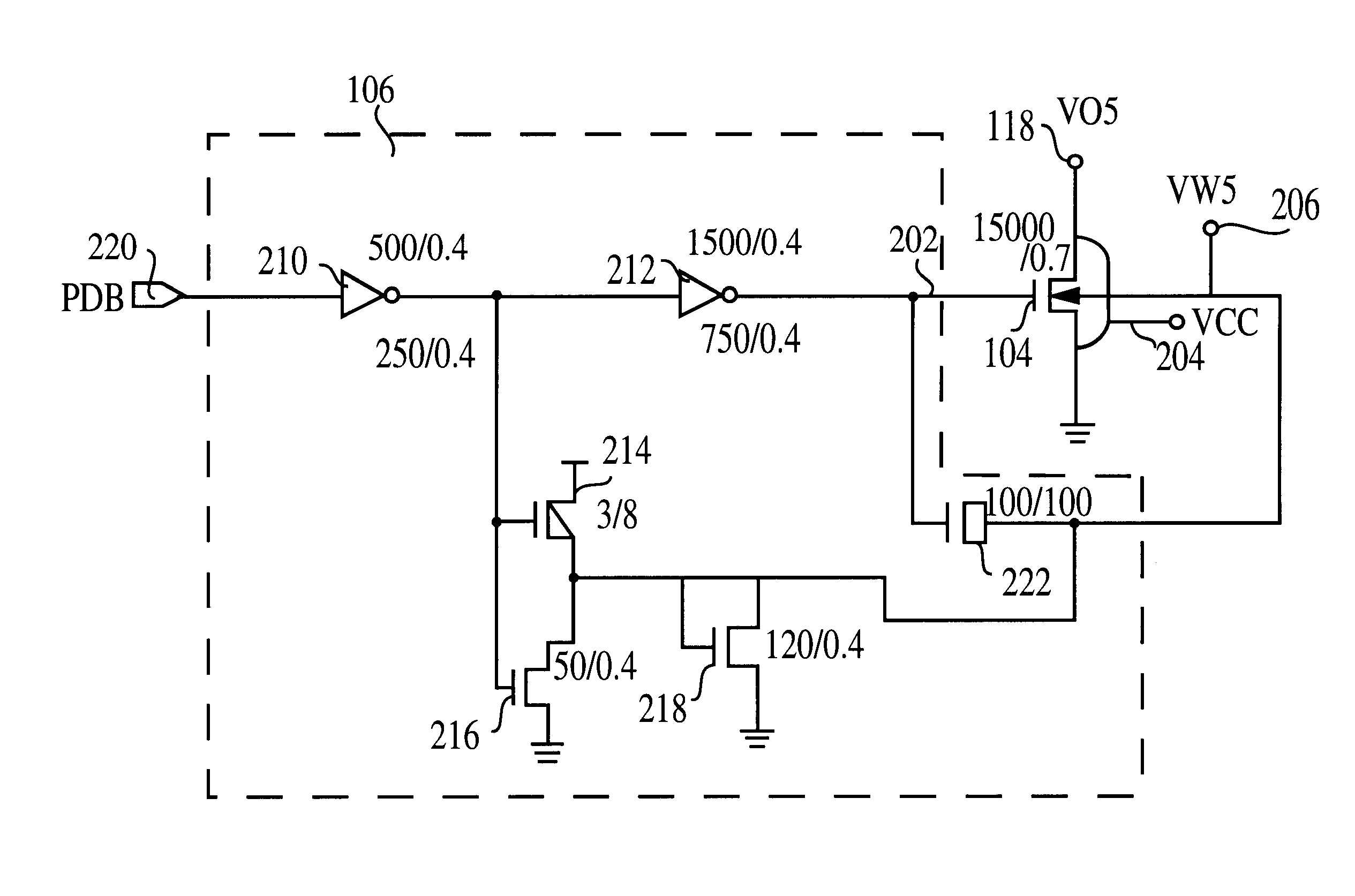
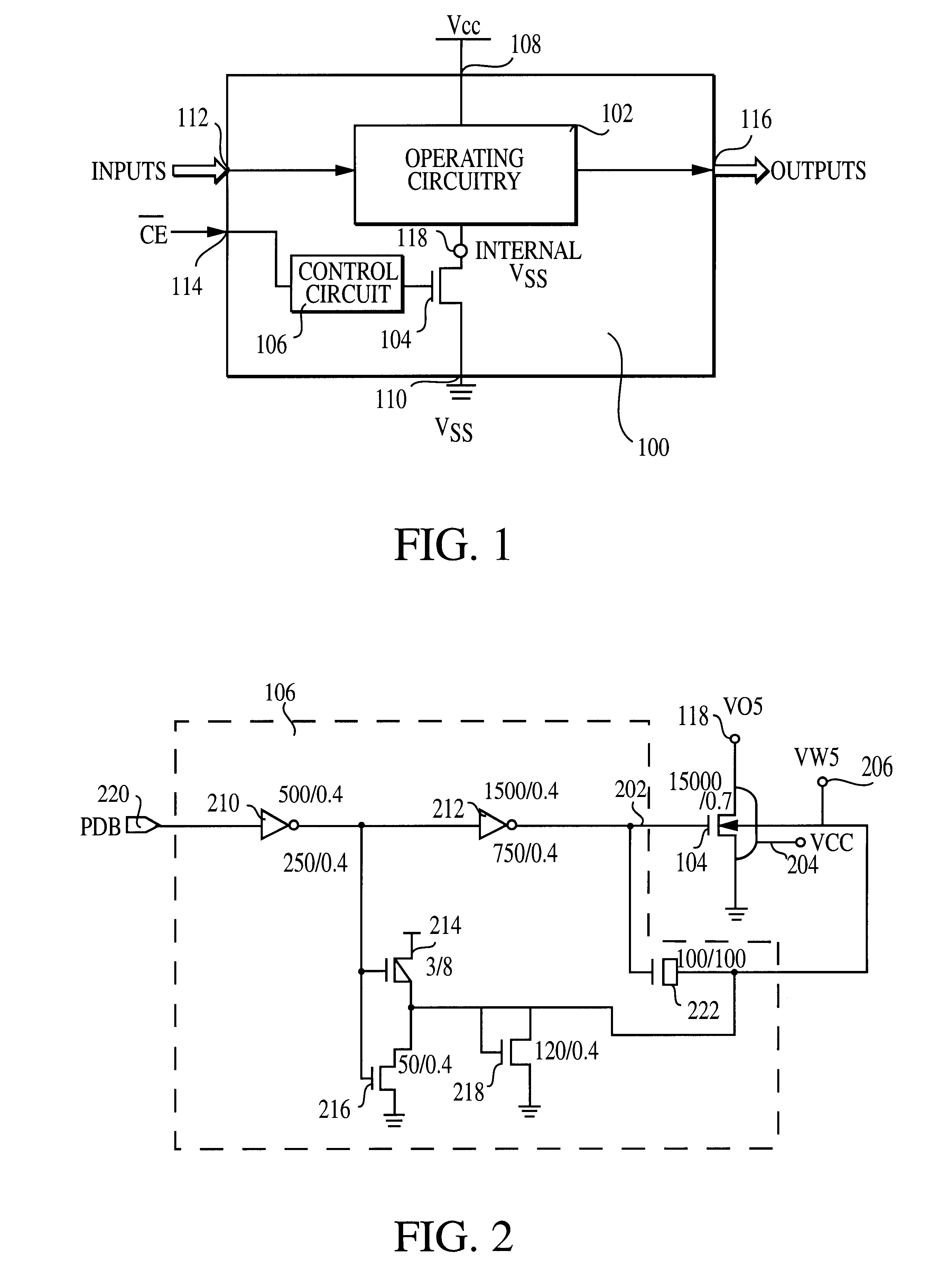
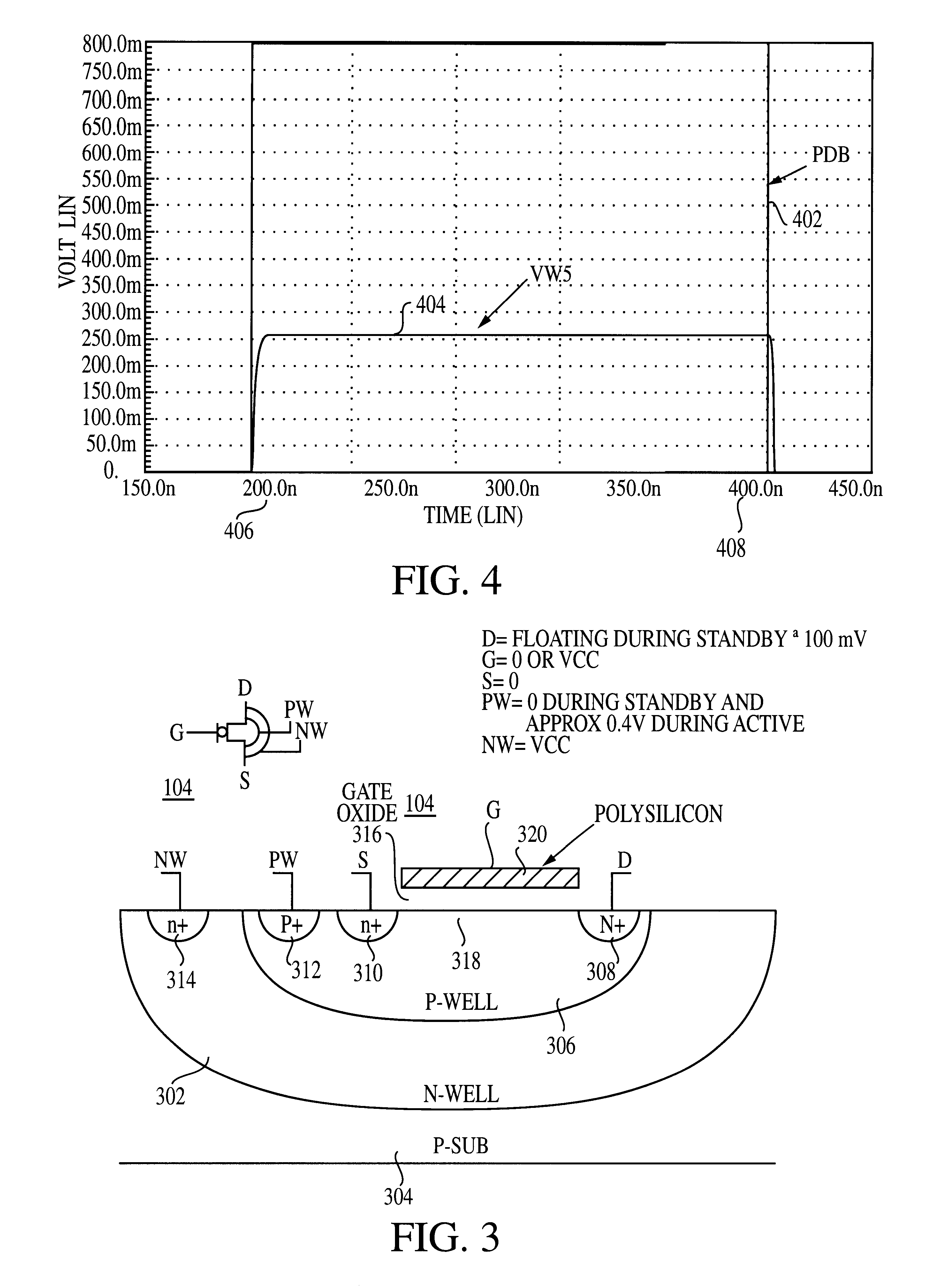
Referring now to the drawing, FIG. 1 is a block diagram of an integrated circuit 100. The integrated circuit 100 may be any integrated circuit manufactured in any suitable technology. In the illustrated embodiment, the integrated circuit 100 is a flash memory chip fabricated using a complementary metal-oxidesemiconductor (CMOS) manufacturing process adapted to low voltage operation. By low voltage, it is meant that the integrated circuit 100 is designed to operate at a very low supply voltage, the supply voltage being defined as the potential difference between a supply voltage level and ground. In the exemplary embodiment, the supply voltage labeled Vcc is nominally 1.0 volts + / -0.1 volts. Further, the supply voltage labeled Vss is nominally ground or zero volts.

The integrated circuit 100 includes operating circuitry 102, a transistor 104, a control circuit 106, a first input 108 configured to receive a first operating voltage, namely the supply voltage Vcc, and a second input 110 ...


PUM


Abstract

An integrated circuit (100) includes a first input (108) to receive a first operating voltage Vcc and a second input (110) to receive a second operating voltage Vss. Operating circuitry (102) of the integrated circuit is coupled to the first input to power the operating circuitry. A transistor (104) is coupled between the second input and the operating circuitry to selectively provide the second operating voltage to the operating circuitry of the integrated circuit. The well containing the transistor is biased to provide a reverse body effect and reduce the threshold voltage of the transistor to allow operation at very low Vcc.

Description

The present invention relates generally to integrated circuit design. More particularly, the present invention relates to circuit design techniques to ensure high-speed, low-power operation at reduced supply voltages in semiconductor memory devices.In the design of integrated circuits, there is a trend to power the integrated circuits using decreasing supply voltage levels. Previous circuit families operated at 5 volts and 3 volts. Current families operate at 1.8 volts and future families will operate at 1.0 volts nominal supply voltage. Under worst case conditions, the supply voltage may be as low as 0.9 volts. These lower supply voltages create design and operation problems.One problem is encountered when adapting conventional complementary metal-oxide-semiconductor (CMOS) circuits for low voltage operation. Conventional n-channel and p-channel transistors have threshold voltages (also called turn-on voltages) too large for satisfactory operation in low voltage applications. For e...

Claims


Application Information

Patent Timeline
IPC IPC(8): G05F1/10G05F1/56H03K19/00
CPCG05F1/562H03K19/0016
Inventor CLEVELAND, LEE EDWARDKIM, YONG
Owner GLOBALFOUNDRIES INC
Learn More