
Image reject mixer, circuit, and method for image rejection

Inactive Publication Date: 2001-05-01
RPX CLEARINGHOUSE
View PDF16 Cites 253 Cited by
  • Summary
  • Abstract
  • Description
  • Claims
  • Application Information

AI Technical Summary

Benefits of technology

Mixing straight down to dc, however, has many advantages since both filtering with low pass filters at dc and digitizing the signal is much easier than at higher frequencies.
If a higher IF is used, then the wanted and image signals may be separated by sufficient frequency (before mixing) to allow the image signal to be attenuated by filtering before mixing. In other words, to allow effective filtering of the image signal, present systems select the IF signal to ensure that the difference frequency (or 2*IF) facilitates filtering, i.e. a distinguishable frequency separation exists between the image signal and the frequency envelope of the wanted signal. In fact, to ensure the filtering can be achieved, the IF needs to be a reasonable fraction of a frequency of the local oscillator (LO). In practice, this means that for digital radios with RF frequencies around 1 GHz (gigaHertz), the IF is currently of such a high frequency that it cannot be simply digitized or filtered. Clearly, the sum component of the IF and the RF signal is easily filterable since it is above the RF band.
Telecommunication standards do, however, require strict compliance to acceptable equipment performance and, in this respect, manufacturers have, to date, opted for a relatively high intermediate frequency in order to reduce manufacturing costs.
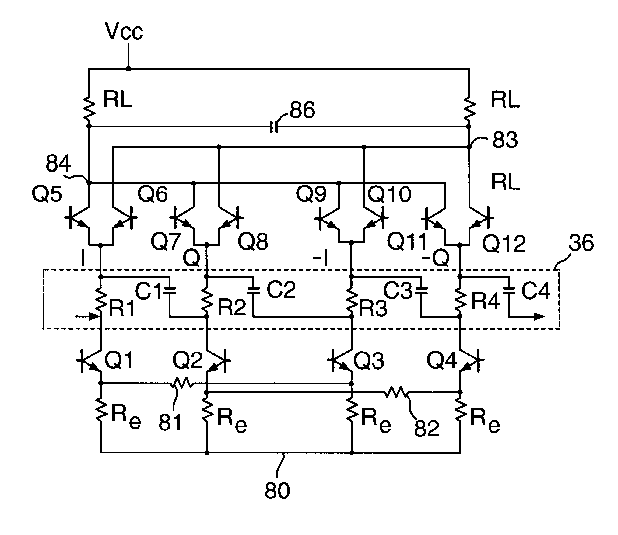
Beneficially, integration of the polyphase filter can be achieved with an overall reduction in the number of components in view (particularly) of the elimination of the requirement to provide discrete buffering components and the advantage that the polyphase filter and the image reject mixer can be current driven (without imposing an increased drain on any available power source, such as a battery). Furthermore, quadrature between each mixer path is therefore improved by direct integration of the polyphase filter, especially in view of the improved component matching achieved within the circuit.
Advantageously, the use of a unitary or (half) channel offset from dc for the IF removes the dc offset problems associated with a zero IF whilst maintaining the receivers ability to benefit from digital processing, including digital filtering. Moreover, use on a unitary channel spacing (particularly) ensures that the image signal lies close to the wanted signal (i.e. in the same system band) but in a frequency domain that allows rejection of a (very) powerful interferer at the image frequency while also reducing the complexity required for subsequent A / D signal conversion.

Problems solved by technology

However, any dc offsets (and, in particular, time varying dc offsets) that occur at the output of a mixer appear as part of the signal, such dc offsets therefore have the unwanted effect of corrupting data integrity.
Unfortunately, these dc offsets cannot be filtered out without removing wanted information in the RF signal.
Consequently, the sensitivity of a receiver is limited by the level of the dc offsets.
The problem with the use of such an intermediate frequency is that the wanted signal at the relatively low IF can be very easily confused with its image signal.
Consequently, the use of an intermediate frequency can result in the incorrect interpretation of data, while elimination of any associated uncertainty is achievable at the cost of the provision of a more accurate quadrature mixer.
In practice, this means that for digital radios with RF frequencies around 1 GHz (gigaHertz), the IF is currently of such a high frequency that it cannot be simply digitized or filtered.
If the IF is too low, then it is impossible to filter the image whilst the signals are at RF.
Clearly, however, the level of suppression is somewhat dependent upon the configuration and type of components (and the manufacturing techniques) employed to construct the image rejection mixer and / or filter and so improved performance can usually be attained through increased manufacturing costs.
However, such increases in cost may render a product commercially non-viable and so performance of the product is therefore often compromised.
Moreover, even in such digital systems, imperfections in conventional filtering and phase noise in local oscillators prevent effective rejection of high level interferers.
To date, therefore, the image reject mixer requires a relatively expensive precision integrated LO quadrature generator.

Method used


Image

  • Image reject mixer, circuit, and method for image rejection
  • Image reject mixer, circuit, and method for image rejection
  • Image reject mixer, circuit, and method for image rejection

Examples


first embodiment

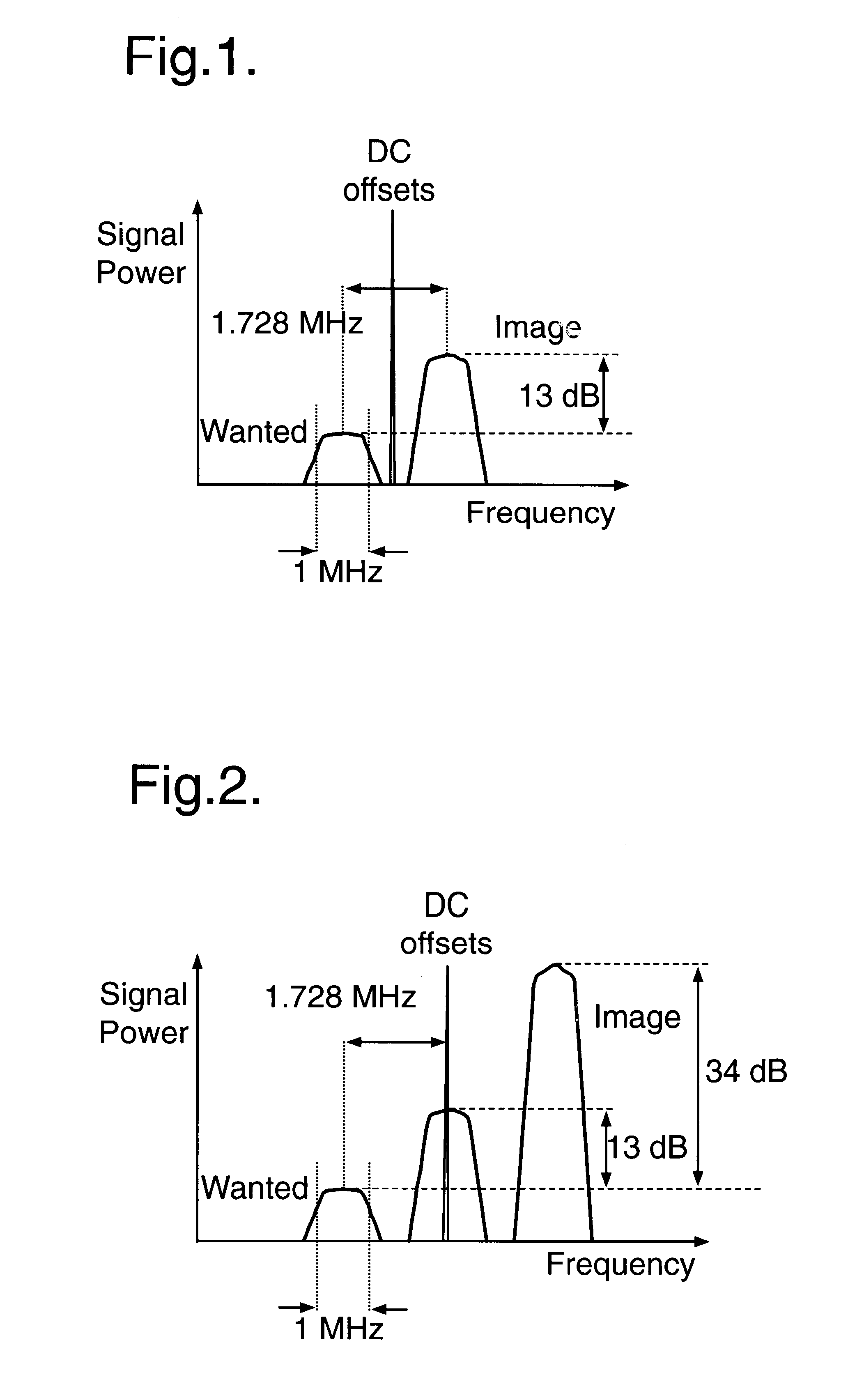
In the present invention, the image is located in the neighbouring channel through the selection of an intermediate frequency that is one half the channel spacing of the telecommunication system (e.g. in DECT, the IF would therefore be selected as 0.5*1.728 MHz, namely at a frequency of 0.864 MHz). DC offsets then sit in the narrow guard band between the wanted channel and its neighbour. An image rejection of 13 dB then reduces the image to the same level as the wanted signal, although a further margin must be allowed to enable low error detection of the signal; this is generally illustrated in FIG. 1.

second embodiment

In the present invention, the IF is selected such that the image falls in the next but one neighbour, i.e. the IF is selected to have unitary channel spacing from dc (e.g. the IF is 1.728 MHz in DECT). The dc offsets then sit on the neighbouring channel and will be removed by conventional channel filtering. An image rejection of 34 dB reduces the image to the same level as the wanted signal, although a further margin must be allowed to enable low error detection of the signal; this is generally illustrated in FIG. 2.

Selection of a one channel offset from dc for the IF is particularly beneficial in relation to the set-up of the synthesizer since key frequencies are all integer multiples thereof. Moreover, digital signal processing is simplified by virtue of the fact that information is kept relative to the base IF frequency (of 1.728 MHz in the specific example of DECT). Indeed, from a demodulation viewpoint, use of the base frequency allows simple mixing to baseband to be achieved w...


PUM


Abstract

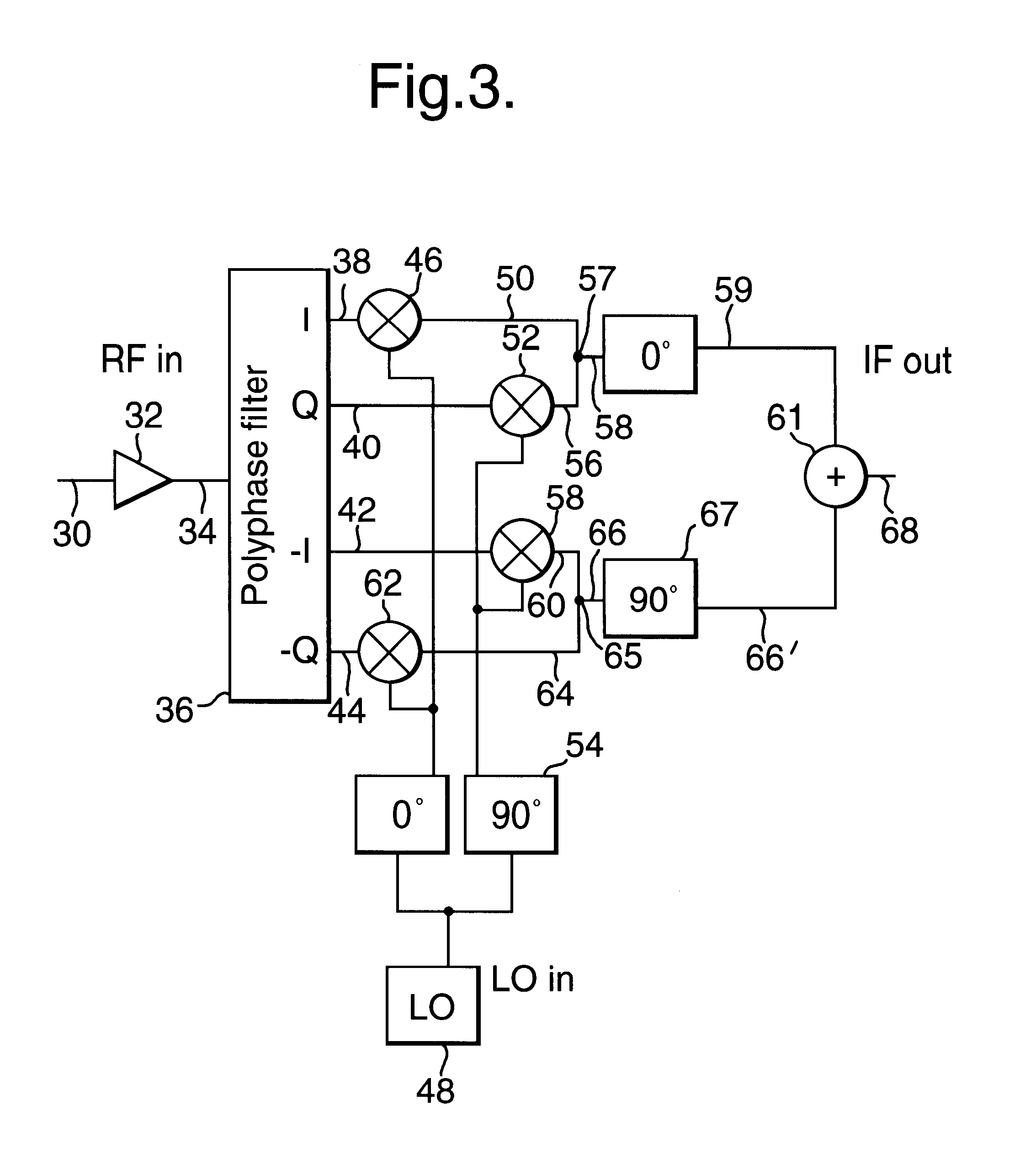
To reduce the impact of image frequencies generated by mixing an incident carrier signal down to a relatively low intermediate frequency signal used in subsequent signal processing, a mixing frequency is selected such that the generated intermediate frequency signal has a frequency offset relative to DC that is substantially that of a single channel spacing between frequency adjacent incident carrier signals, as shown in FIG. 2. Image rejection is further improved through the integration of a current-driven polyphase filter (36) directly between an input stage (Q1 to Q4) and a mixer stage (Q5 to Q12) of an image reject mixer (FIG. 4) such as to mitigate quadrature divergence between separate in-phase and quadrature paths within the image reject mixer.

Description

This invention relates, in general, to a circuit and operating method for image rejection and also to the configuration of an image reject mixer. More particularly, but not exclusively, the invention is applicable to integrated circuit technology for a radio communication device, such as a Digital Enhanced Cordless Telecommunication (DECT) chip-set.SUMMARY OF THE PRIOR ARTWith an increasing demand by the general public for smaller and more ergonomic designs, telecommunication equipment (and particularly subscriber / handset) manufacturers have sought higher levels of functional integration within their respective integrated circuit (IC) designs. Indeed, subscriber terminals, for example, can now be realized through the use of as little as two ICs (which are sometimes referred to as "chips"). However, in order to achieve this level of integration, manufacturers' have had to develop improved circuitry that consumes relatively low amounts of power (typically driven by a voltage at or bel...

Claims


Application Information

Patent Timeline
IPC IPC(8): H03D7/18H03D7/00H03D7/14H04B1/28H03D7/16
CPCH03D7/1433H03D7/165H03D7/18H04B1/28H03D7/1458H03D2200/0033H03D2200/0043
Inventor MOLE, PETER JOHNVAN VLIET, HENRICBABLA, CHETTAN
Owner RPX CLEARINGHOUSE
Learn More