Method and apparatus for performing data sorting in a decoder

a decoder and data sorting technology, applied in the field of telephone conversation high bit rate receivers, can solve the problems of low bit rate, low bit rate, and low bit rate, and achieve the effect of high bit ra

Inactive Publication Date: 2001-05-15
METALINK LTD
View PDF2 Cites 18 Cited by
  • Summary
  • Abstract
  • Description
  • Claims
  • Application Information

AI Technical Summary

Benefits of technology

It is an object of the present invention to provide an improved, high bit rate receiver for telephone conversations which operates on signals having intersymbol interference, NeXT cross-talk and any uncancelled echo information.

Problems solved by technology

As a result, the pulses are delayed and also spread out in time which means that their amplitude diminishes over time.
Furthermore, the communication channel is noisy, typically from cross-talk due to the fact that many conversations are carried over the same telephone cable.
However, if any one decision was incorrect, the later decisions may be incorrect.
The MLSE is the optimal receiver for channels with ISI; however, the MLSE increases in complexity as a function of the channel memory and the size Q of the symbol alphabet.
Therefore, the MLSE is not practical for implementation in a real-time, high data rate communication channels with large channel memories and a symbol alphabet larger than 2.
All of these RSSE estimators are complex due to the number and size of the sequences to be calculated.
Furthermore, the estimators described do not provide significantly better results to compensate for their increased complexity over standard ISI reducing units.

Method used


Image

  • Method and apparatus for performing data sorting in a decoder
  • Method and apparatus for performing data sorting in a decoder
  • Method and apparatus for performing data sorting in a decoder

Examples


Embodiment Construction

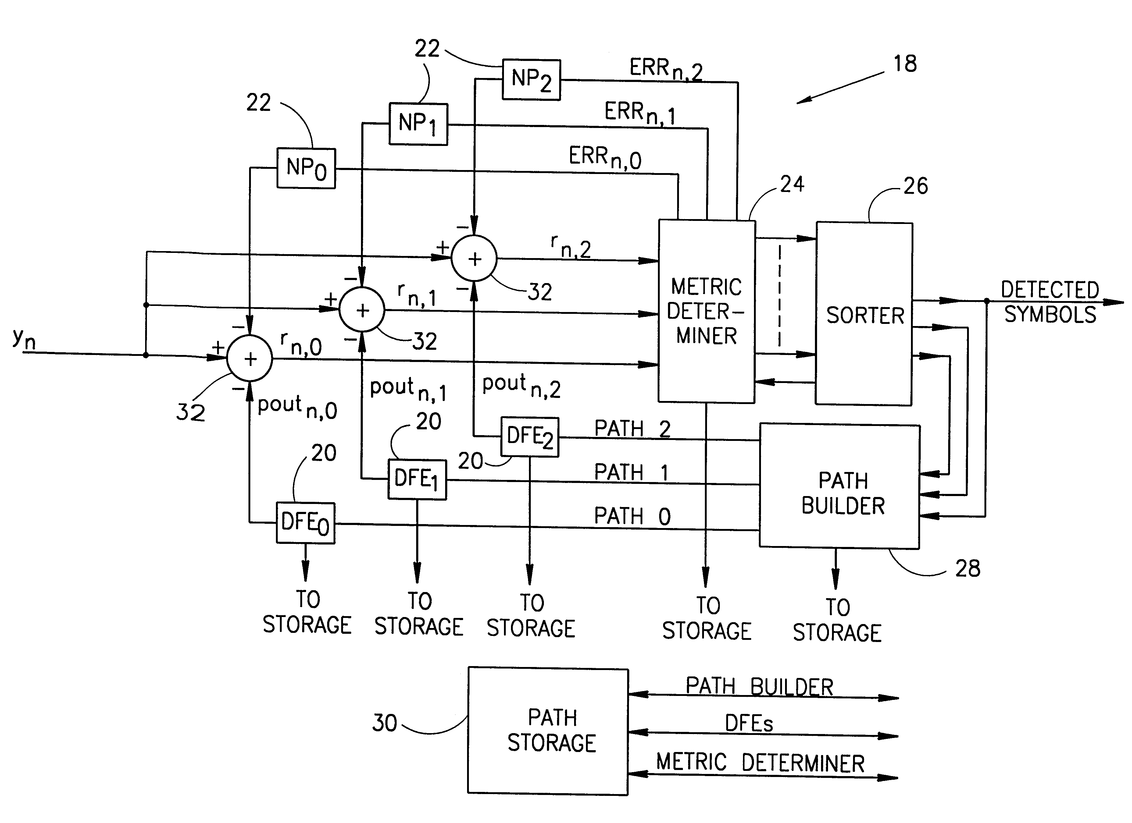
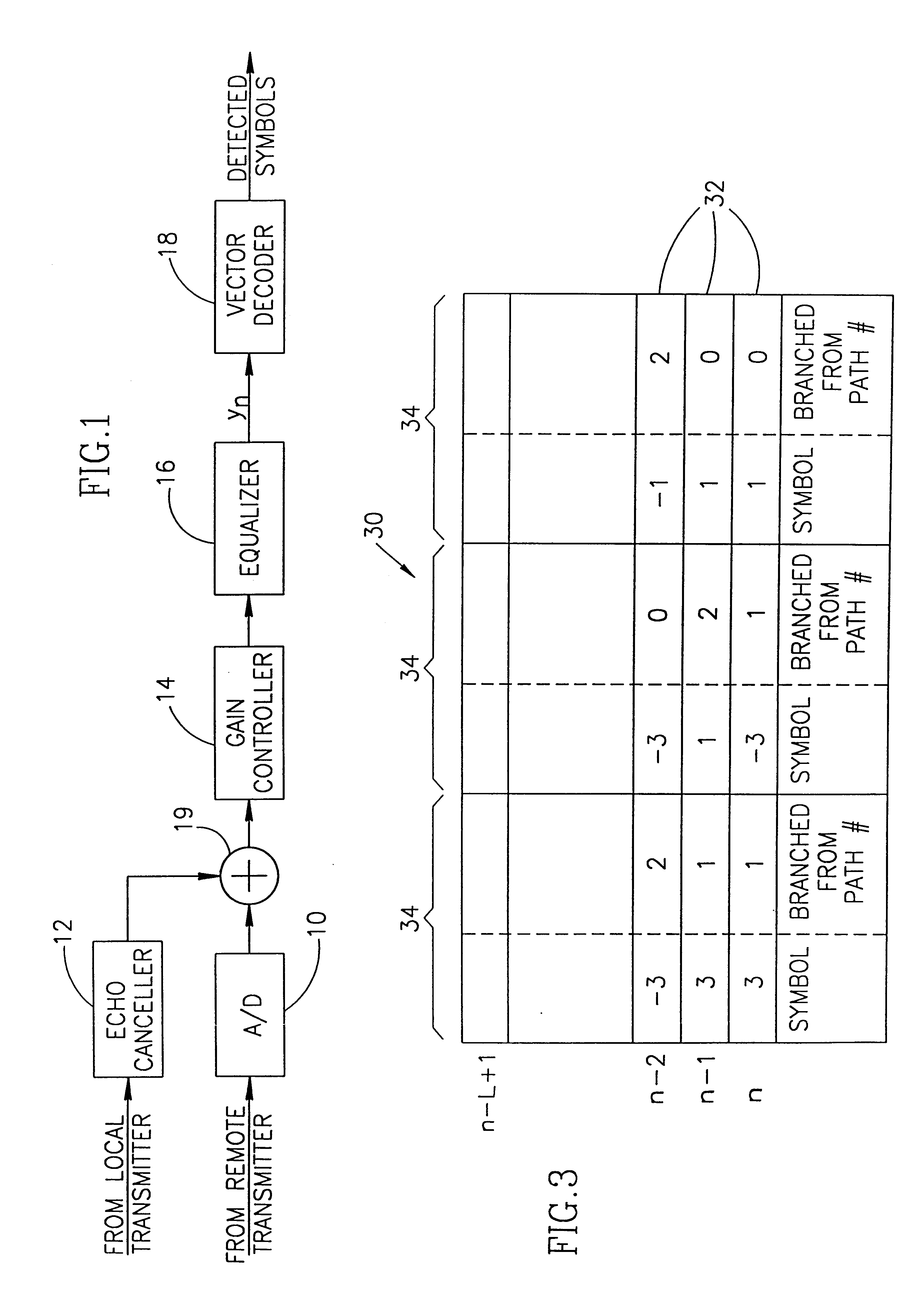
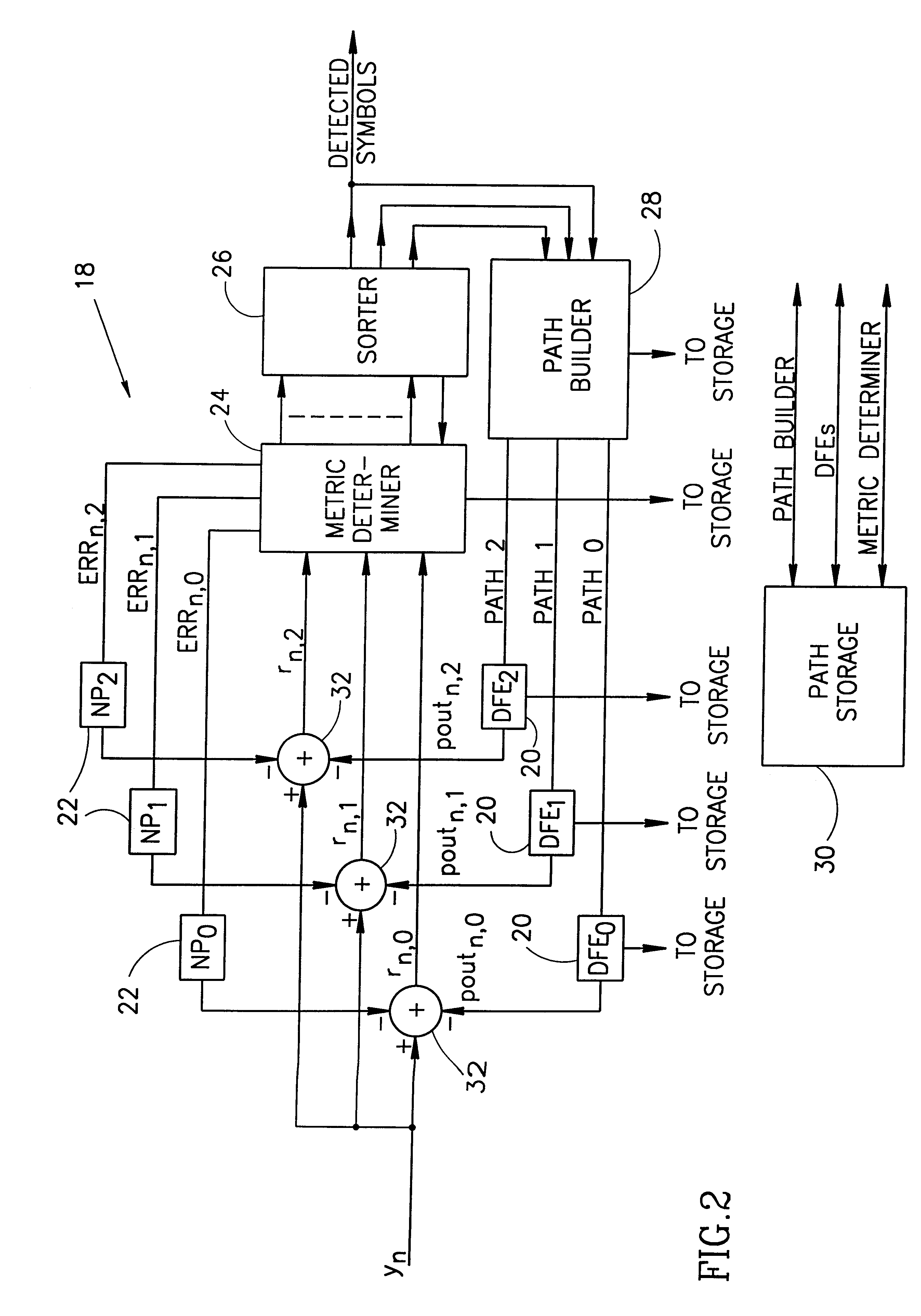
Reference is now briefly made to FIG. 1 which illustrates a standard, full duplex, data communications receiver. The receiver comprises an analog-to-digital converter 10, an echo canceller 12, a gain controller 14, a linear equalizer 16 and a vector decoder 18. The A / D converter 10 receives an analog, modulated signal from a remote transmitter (the signal to be decoded) and converts it to a digital modulated signal. The analog signal comprises the symbols to be decoded as well as echoes and noises. The analog signal can be sent along any type of communication channel; for example, it can be sent along copper loops or via satellite. The communication can be with binary modulation (symbol values of 1 and -1), 2B1Q modulation (e.g. symbol values of -3, -1, 1, 3) or any other Q-ary modulation method.

The local transmitter, not shown, transmits a signal at the same time that the receiver receives a signal. Since the two signals (incoming and outgoing) travel along the same physical line, ...


PUM


Abstract

A vector decoder for detecting symbols transmitted along a communication channel is disclosed, as is a method for decoding symbols. The decoder includes at least two pairs of decision feedback equalizers and noise predictors operating on a plurality M of vectors of symbols being detected, a path storage unit, a metric determiner a sorter and a path builder. The vectors are ordered in accordance with quality levels and each noise predictor estimates the noise associated with its associated vector. The path storage unit stores M of the ordered vectors, each vector being of length L. The metric determiner is connected to the output of all of the decision feedback equalizers and the noise predictors and produces a performance metric for each of Q branches extending from each vector. Each branch is associated with one of Q possible symbol values. The sorter is connected to the output of the metric determiner and sorts data, formed of a) the symbol values and b) the vectors which they extend, in accordance with their performance metrics. The sorter also orders, from the M*Q performance metrics, the data having the M best performance metrics. The path builder is connected to the output of the sorter and associates the ordered data with the appropriate ones of the previously stored ordered vectors.

Description

The present invention relates to symbol decoders in data communication receivers and to symbol decoders for high bit rate digital subscriber loop (HDSL) receivers.The demand for fast and reliable transmission of digital information has encouraged the development of many different types of communication transceivers (a transmitter and receiver in one element) which efficiently employ the minimal bandwidth of telephone lines. One such communication technique is quadrature amplitude modulation (QAM) and another is pulse-amplitude modulation (PAM).For both techniques, a sequence of equally likely data symbols is transmitted as pulses over the communication channel at a fixed symbol rate which is significantly above than the bandwidth of the communication channel. As a result, the pulses are delayed and also spread out in time which means that their amplitude diminishes over time. The signal which is received by the receiver is a superposition of the pulses over time. The "memory" of a c...

Claims


Application Information

Patent Timeline
Patent Type & Authority Patents(United States)
IPC IPC(8): H04L25/49H04L25/03
CPCH04L25/03057H04L25/03267H04L25/4919
Inventor SHUKHMAN, TZVIKLIGER, AVIILEVITZKY, AMIR
Owner METALINK LTD
Why Eureka
Try Eureka